SERIE XRB80N100
- Fuente de alto voltaje con alimentación de filamento, tubo de rayos X, puerto de haz y electrónica de control integrados
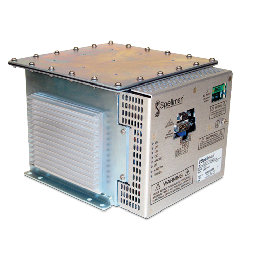
- Compacta y ligera
- Entrada universal, factor de potencia corregido con filtro interno de interferencia electromagnética
- Se puede montar en cualquier orientación física
- Interfaz de control analógica e interfaz de control digital estándar RS-232
80kV, 100W X-Ray Source
La fuente X-Ray XRB80N100 Monoblock® de Spellman está diseñada para aplicaciones OEM que alimentan su tubo de rayos X interno de hasta 80 kV a 100 W. Características como la entrada universal, el tamaño pequeño del paquete y una interfaz analógica estándar y digital RS-232 simplifican la integración de esta unidad en su sistema de rayos X. El XRB80N100 está disponible con geometrías de haz en forma de abanico (estándar) o (opcional) cono. Los circuitos patentados de control de emisiones proporcionan una excelente regulación de la corriente del tubo de rayos X, junto con un rendimiento de estabilidad excepcional.
Aplicaciones típicas:
- Barrido de rayos X: densitometría ósea
- Medición de espesores
- Inspección de alimentos
- Confirmación de nivel de llenado
- Inspección de paquetería
![]()
Especificaciones
(Ref. 128065-001 REV. Y)
X-Ray Characteristics:
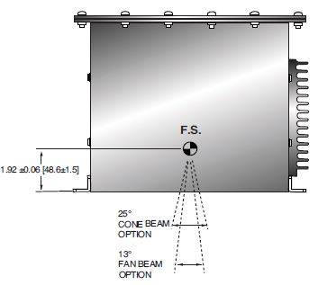
Focal Spot: 0.5mm (IEC 336)
Beam Filter:
Ultem: 3.30mm ±0.15mm
Oil: 8mm ±0.1mm
Glass: 1.8mm ±0.25mm
BE: 0.8mm
Beam Geometry:
Fan: Standard. The beam angular coverage will be 75° with the beam plane perpendicular to the X-Ray tube axis and 13° wide.
Cone: Optional. 25° cone beam
Input Voltage:
Power factor corrected input 0.98, 100-240Vac ±10% 50/60Hz, 2A, maximum
X-Ray Tube Voltage:
Nominal X-Ray tube voltage is adjustable up to 80kV
X-Ray Tube Current:
150uA to 1.25mA over specified tube voltage range
X-Ray Tube Power:
100W, maximum continuous
Voltage Regulation:
Line: ±0.05% of maximum output voltage over a ±10% change of nominal input line voltage
Load: ±0.1% of maximum rated voltage for 150uA to 1.25mA load change
Voltage Accuracy:
Voltage measured across the X-Ray tube is within ±2% of the programmed value
Voltage Risetime:
Standard: Ramp time shall be 500ms from 10% to 90% of maximum rated output voltage
Optional: 5 seconds. Specify at time of order
Voltage Overshoot:
5% of maximum voltage, to return within 2.5% of maximum voltage in less than 100ms
Voltage Ripple:
1% peak to peak of maximum voltage for frequencies ≤ 1kHz
Emission Current Parameters
Current Regulation:
Line: ±0.05% of rated output current over a ±10% change of nominal input line voltage
Load: ±0.1% of rated output current for a change from 50% to 100% of rated output voltage
Current Accuracy:
Current measured through the X-Ray tube is within ±2% of the programmed value
Current Risetime:
Standard: Ramp time shall be 500ms from 10% to 90% of maximum rated current
Optional: 5 seconds. Specify at time of order
Arc Intervention:
3 arcs in 10 seconds with a 200ms quench = Shutdown
Filament Configuration:
Internal high frequency AC filament drive with closed loop filament emission control
Analog Interface:
Ground referenced 0 to 9Vdc for all programming and monitoring signals. Relay contacts and open collector signals for other signals. See analog interface connector pin out table.
Digital Interface:
Jumpers are needed to be configured and the digital interface cable installed to enable the RS-232 interface.
Control Software:
A demo GUI is available for engineering evaluations
Interlock/Signals:
A hardware interlock functions in both analog and digital programming modes. The hardware X-Ray Enable signal only functions in analog programming mode.
Operating Temperature:
0°C to +40°C
Storage Temperature:
-40°C to +70°C
Humidity:
10% to 95% relative humidity, non-condensing
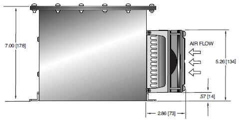
Cooling:
Customer provided 150cfm external cooling fan as required to maintain oil temperature below 55°C. (External cooling is not required if fan option is selected)
Input Line Connector:
3 pin, Phoenix Contact 1829167, SHV part number 105725-219. Mating connector Phoenix Contact #1805990, SHV part number 105808-475 provided with unit.
Analog Interface Connector:
15 pin D connector, male
Digital Interface Connector:
9 pin D connector, female
Grounding Point:
8-32 ground stud provided on chassis
Dimensions:
9.6.L X 7.6.W X 7.0.H (243.8mm x 193.0mm x 177.8mm)
Weight:
32lbs (14.5kg)
Orientation:
Can be mounted in any orientation.
X-Ray Leakage:
Not to be greater than 0.5mR/hr at 5cm outside the external surface.
Regulatory Approvals:
Compliant to EEC EMC Directive. Compliant to EEC Low Voltage Directive. UL/CUL recognized file E235530.
OPTIONS
RT - 5 second Risetime for both voltage and current
CB - Cone Beam
FN - Integrated Cooling Fan
M - Elapsed Time Meter (measures X-Ray ON elapsed time)
AC LINE POWER CONNECTOR— J1 THREE POSITION PHOENIX CONTACT
| Pin | Signal |
|---|---|
| 1 | Earth Ground |
| 2 | Line |
| 3 | Neutral |
Mating connector provided with unit
RS-232 DIGITAL INTERFACE— J3 9 PIN FEMALE D CONNECTOR
| Pin | Signal | Parameters |
|---|---|---|
| 1 | N/C | No Connection |
| 2 | TD | Transmit Data |
| 3 | RD | Receive Data |
| 4 | N/C | No Connection |
| 5 | SGND | Signal Ground |
| 6 | NC | No Connection |
| 7 | NC | No Connection |
| 8 | NC | No Connection |
| 9 | NC | No Connection |
XRB ANALOG INTERFACE— J2 15 PIN MALE D CONNECTOR
| Pin | Signal | Parameters |
|---|---|---|
| 1 | Power Supply Fault Output | Open collector, 35V @ 10mA max. high = no fault |
| 2 | mA Program Input | 0 to 9.00Vdc = 0 to 100% rated output, Zin =10MΩ |
| 3 | kV Program Input | 0 to 9.00Vdc = 0 to 100% rated output, Zin =10MΩ |
| 4 | X-Ray On Lamp Relay Output | Common, dry contacts, 30Vdc @ 1A, max |
| 5 | X-Ray On Lamp Relay Output | Normally open, X-Ray ON = closed |
| 6 | mA Monitor Output | 0 to 9Vdc = 0 to 100% rated output, Zout =10kΩ |
| 7 | X-Ray On Lamp Relay Output | Normally closed, X-Ray ON = open |
| 8 | kV Monitor Output | 0 to 9.00Vdc = 0 to 100% rated output, Zout =10kΩ |
| 9 | Signal Ground | Ground |
| 10 | Signal Ground | Ground |
| 11 | HV Interlock Return Input | Connect to Pin 12 to close HV interlock |
| 12 | HV Interlock Output | +15Vdc @ open, 5mA when connected to pin 11 |
| 13 | X-Ray Enable Output | +15Vdc @ open, 5mA when connected to pin 15 |
| 14 | X-Ray Status Output | Open collector, 35V @ 10mA max high = X-Ray OFF |
| 15 | X-Ray Enable Return Input | Connect to pin 13 to enable X-Ray generation |
LED INDICATORS
| Indicator | Signal Name | Condition Illuminated When... |
|---|---|---|
| LED 1 | OV | High kV occurs |
| LED 2 | UV | Low kV occurs |
| LED 3 | UC | Low mA occurs |
| LED 4 | OC | High mA occurs |
| LED 5 | ARC FLT | Arc fault occurs |
| LED 6 | OT | Over temperature occurs |
| LED 7 | X-RAY ON | X-Rays are enabled |
| LED 8 | PWR | Power is ON |
| How to Order: |
|---|
| Standard: Prt No.: XRB80N100 |
|
Risetime, Cone Beam, Fan and Elapsed Time Meter Options |
Tablas y Diagramas
DIMENSIONS: in.[mm]
Standard Unit
FRONT VIEW
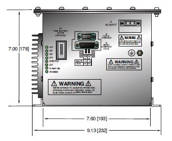
BACK VIEW
SIDE VIEW
BOTTOM VIEW
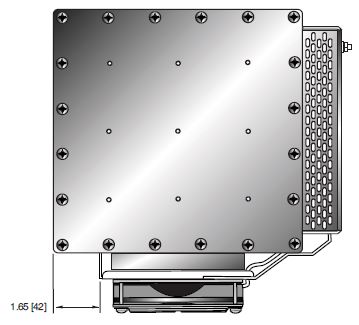
DIMENSIONS: in.[mm]
Cooling Fan Options
TOP VIEW
SIDE VIEW

BACK VIEW