SERIE CCM1KW
- Paquete compacto y ligero
- Entrada corregida de factor
- Plataforma modular costeable para OEM
- Topología de inversor resonante de conmutación suave
- Reconocimiento UL/CUL, cumple con RoHS
*Nota: Todas las especificaciones están sujetas a cambios sin previo aviso. Consulte la versión en PDF en inglés de esta hoja de datos para obtener la revisión más actualizada.
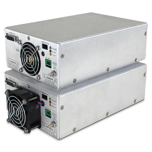
MÓDULO DE CARGA DE CAPACITORES DE 1 KW
El módulo de carga de capacitores CCM1KW de Spellman está diseñado para proporcionar hasta 1000 joules por segundo y un voltaje de salida de hasta 4000 voltios. La entrada de CA de factor de potencia corregido, el tamaño de paquete pequeño y las interfaces analógicas detalladas y mínimas simplifican la integración de la CCM1KW en el diseño de su sistema de aplicación OEM. Disponible en polaridad positiva o negativa, el CCM1KW está protegido por completo contra arcos, cortocircuito y circuito abierto. Las unidades pueden operar en paralelo para aplicaciones que requieren potencia superior (consultar el manual para detalles)
Aplicaciones típicas:
- Fuentes de luz UV para curado y esterilización industrial y aplicaciones de láser médico
Especificaciones
(Ref. 128103-001 REV. K)
Input Voltage:
90-264 Vac, 50/60 Hertz, power factor corrected input ≥0.98
Input Current:
14 Amps worst case, 1000 Joules per second
7 Amps worst case, 500 Joules per second
Efficiency:
>85%
Output Power:
1000 Joules per second, 500 Joules per second
Output Voltage:
0-1kV, 0-2kV and 0-4kV version available
Output Polarity:
Positive or negative, specify at time of order
Stored Energy:
Less than 0.2 Joules
Pulse to Pulse Repeatability:
±0.2% up to 1kHz
Temperature Coefficient:
≤ 100ppm per degree C
Fault Diagnostic System:
Over Temperature and Over Voltage Over Voltage Fault is latched requiring AC power recycle to clear. Over Temperature Fault is latched but can be cleared via inhibit/fault reset line.
Environmental:
Temperature Range:
Operating: 0°C to 40°C
Storage: -40°C to 85°C
Humidity:
10% to 90% RH, non-condensing
Cooling:
Forced air
Input Line Connector:
2 position Phoenix MSTB connector, straight and right angle mating connector provided
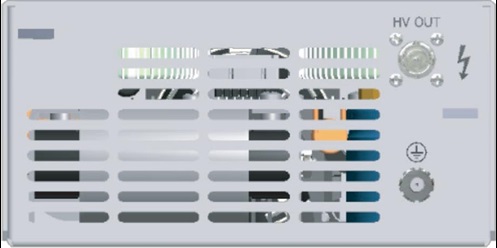
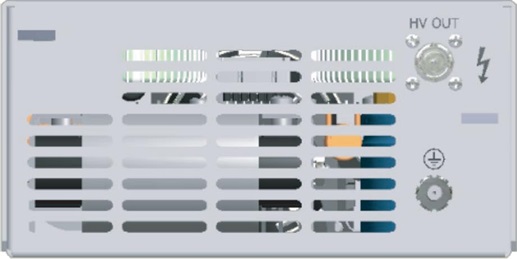
HV Output Connector:
Standard: Kings/Winchester Electronics SHV 1707-1
Optional: Amphenol MHV UG-931/U
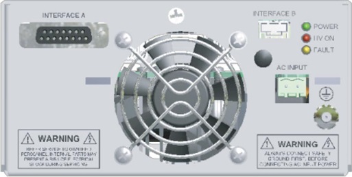
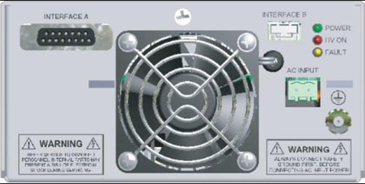
Interface-A Connector:
15 pin D, female
Interface-B Connector:
4 pin male Molex 705530038
Ground Stud:
10-32, nut supplied
Dimensions:
3. H X 6. W X 9. D (76.2mm x 152.4mm x 228.6mm)
Mounting:
M4 screw. Max. depth is 0.188. (4.78mm)
Weight:
6.9lb. (3.13kgs)
Regulatory Approvals:
Compliant to 60601-1-1. Compliant to 60601-1-2. UL/CUL recognized file E242584. RoHS compliant.
AC INPUT–2 POSITION TERMINAL BLOCK
| Pin | Signal | Signal Parameters |
|---|---|---|
| 1 | AC Input High/Phase 1 | Line Hot/Phase 1 |
| 2 | AC Input Low/Phase 2 | Line Neutral/Phase 2 |
ANALOG INTERFACE A— 15 PIN FEMALE D CONNECTOR
| Pin | Signal | Signal Parameters |
|---|---|---|
| 1 | Inhibit/Fault Reset | Ground = HV Enable, Open/+15Vdc = HV Inhibit |
| 2 | N/C | N/C |
| 3 | OverTemp Fault | No OT Fault = +15Vdc @ 3mA, OT Fault = Ground |
| 4 | Signal Ground | Signal Ground (optional)* |
| 5 | Voltage Program | 0 to 10Vdc = 0 to 100% rated output voltage |
| 6 | Overvoltage Status | No OVP = +15Vdc @ 3mA, OVP Fault = Ground |
| 7 | Peak Hold Monitor | Peak output voltage displayed, 0 to 10Vdc = 0 to 100% rated output voltage with a 5 second time constant |
| 8 | Voltage Monitor | 0 to 10Vdc = 0 to 100% rated output voltage, ±1% |
| 9 | +15Vdc | +15Vdc @ 150mA, maximum** |
| 10 | N/C | N/C |
| 11 | +15Vdc | +15Vdc @ 150mA, maximum (optional)** |
| 12 | Signal Ground | Signal Ground (optional)* |
| 13 | End of Charge | Charging = +15Vdc @ 1.5mA, End of Charge = Ground |
| 14 | Signal Ground | Signal Ground |
| 15 | Signal Ground | Signal Ground |
Note: Output status signals are NMOS transistor controlled, 100mA maximum sink current. Actual signals are 5kΩpull ups to the internal +15Vdc logic source.
*Optional interface signals can be provided to be compatable with other pre-existing legacy interfaces. On standard units these signals are N/C.
**+15Vdc ±10% is provided on the standard unit. Optional +12Vdc ±5%/100mA, maximum can be provided.
INTERFACE B–4 PIN MALE D HEADER
| Pin | Signal | Signal Parameters |
|---|---|---|
| 1 | Inhibit/Fault Reset | Ground = HV Enable, Open/+15Vdc = HV Inhibit |
| 2 | Signal Ground | Signal Ground |
| 3 | Voltage Program | 0 to 10Vdc = 0 to 100% rated output voltage |
| 4 | +15Vdc | +15Vdc @ 150mA, maximum (optional)* |
CCM1KW SELECTION TABLE kV JOULES/SECOND
| kV | Joules/Second | |
|---|---|---|
| 1 | 500 | CCM1*500 |
| 2 | 500 | CCM2*500 |
| 4 | 500 | CCM4*500 |
| 1 | 1000 | CCM1*1000 |
| 2 | 1000 | CCM2*1000 |
| 4 | 1000 | CCM4*1000 |
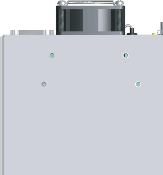
*Specify P for positive or N for negative 500 J/s units have a single internal fan, 1000 J/s units have both an internal and external fan.
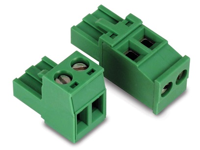
Straight and right angle AC input mating connectors are provided
Tablas y Diagramas
500 Joules per second
(unit with internal fan)
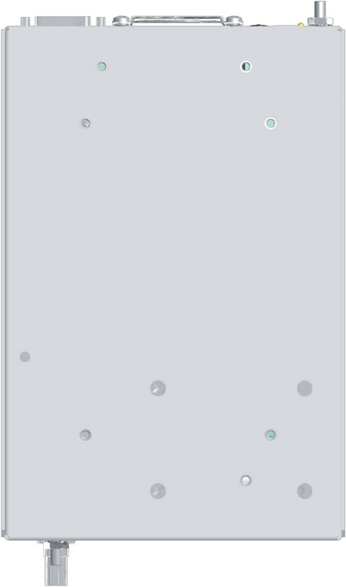
DIMENSIONS: in.[mm]
REAR VIEW
FRONT VIEW
BOTTOM VIEW
1000 Joules per second
(unit with internal and external fan)
DIMENSIONS: in.[mm]
REAR VIEW
FRONT VIEW
BOTTOM VIEW
Frequently Asked Questions
What Is a Safe Level of High Voltage?
Where Can I Obtain Information on High Voltage Safety Practices?
How Should I Ground Your Supply?
Why Do I Have to Fill Out a Capacitor Charging Questionnaire If I’m Going to Use Your Power Supply for Capacitor Charging?

