XRB200PN400/2
- 200kV and 400W
- X-Ray Tube Current: 0.5mA to 2.0mA @ 200kV
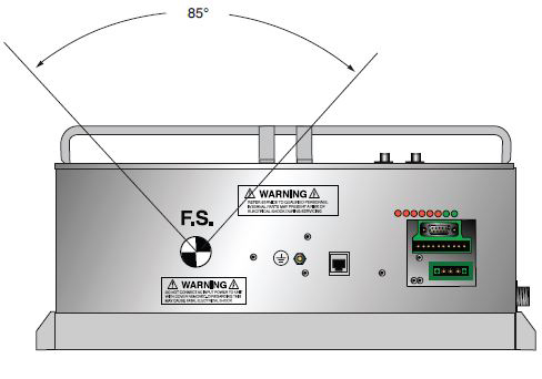
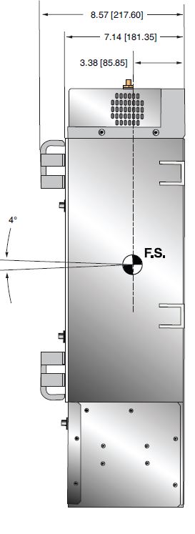
- Symmetrical fan beam of 85° X 4°, ±1%
- Power factor corrected input to 0.98
- 100Vac to 240Vac, ±10%
- Logging and Firmware Controlled X-Ray Tube Seasoning
*Note: All specifications are subject to change without notice. Please consult the English PDF version of this datasheet for the most up-to-date revision.
XRB200PN400/2
Spellman’s XRB200PN400/2 is an integrated X-Ray source operating up to 200kV and 400W, providing OEM users a compact plug-and-play Monoblock® for critical inspection and screening applications. The unit incorporates a 15° angle stationary anode X-Ray tube offering a symmetrical fan beam of 85° X 4°. Proprietary emission control circuitry provides excellent regulation of X-Ray tube current, with industry leading dose stability and image quality. This compact model comes with standard analog and RS-232 digital control. Spellman can provide customized versions of this platform for specific OEM system requirements.
TYPICAL APPLICATIONS
Aviation Security Screening: Checked Baggage/EDS Vehicle Inspection, Cargo Inspection, General NDT
사양
(Ref. 128085-001 REV. B)
X-Ray Characteristics:
Tube Type: Stationary Anode, tungsten target
Focal Spot: 0.8 x 0.8mm nominal (IEC60336)
Beam Filter: Glass 2.1mm, maximum. Oil 18mm.
Beam Geometry: Symmetrical fan of 85° X 4°, ±1%
Anode Angle: 15°
Input Voltage:
Power factor corrected input to 0.98. 100Vac to 240Vac, ±10%, 50/60 Hertz. 6 Amps, maximum
X-Ray Tube Voltage:
Nominal X-Ray tube voltage is adjustable between 100kV to 200kV
Voltage Accuracy:
The high voltage measured at the X-ray tube will be within ±1% of the selected value.
Voltage Ripple:
Ripple will be 1% of maximum rated voltage for frequencies ≤1kHz.
Voltage Regulation:
< ±0.1% for ±10% of nominal input line change
< ±0.1% for 0.5mA to 2mA load change
Voltage Overshoot:
kV overshoot will return within 5% of full voltage in less than 100ms.
Risetime:
The voltage and current risetime is controlled by a ramping circuit. Ramp time is less than 1.0 second from 10% to 90% of output voltage and current.
X-Ray Tube Current:
0.5mA to 2.0mA @ 200kV, 400 watts maximum
Current Accuracy:
<±1% of the selected value.
Current Regulation:
<0.5% at 100 - 200 kV, 0.5mA to 2.0mA
Arc Intervention:
Unit will detect a single arc but HV will not shut down. If multiple arcs occur (4 in 10 seconds) then the unit will shut down.
Filament Configuration:
Isolated high frequency AC filament drive operated in current mode with closed loop thermionic filament emission control.
Digital Interface:
The RS-232 and Ethernet interfaces allow for programming of the voltage, current and X-Ray Enable. Provides monitoring for voltage, current and oil temperature. Tolerance is 3%.
Control Software:
A demo GUI is available for engineering evaluation.
Operating Temperature:
0°C to +40°C
Storage Temperature:
-40°C to +70°C
Humidity:
10% to 95% relative humidity, non-condensing.
Cooling:
Heat exchanger with fan and oil pump. Customer provided +24Vdc @ 3A is required. In certain situations, external cooling fans of 250CFM may be required to maintain tank/oil temperature below 55°C.
Input Line Connector:
3 pin Phoenix Contact, p/n 1829167. Mating connector provided with unit.
Analog Interface Connector:
10 pin Phoenix Contact, p/n 1755503. Mating connector provided with unit.
RS-232 Connector:
9 pin female D connector. Mating connector provided with unit.
Ethernet Connector:
8 pin RJ45 connector.
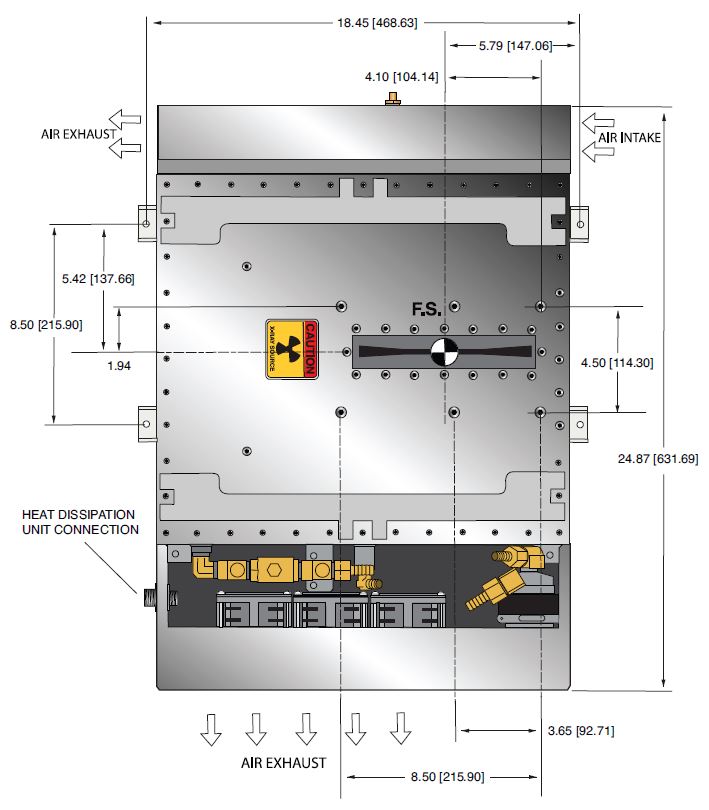
Heat Dissipation Unit Connector:
4 pin AMP connector, TE Connectivity (206061-1) Mating connector provided with unit.
Grounding Point:
M4 grounding stud provided on chassis.
Dimensions:
See outline drawing.
Weight:
181 pounds (80kg).
Orientation:
Can be mounted in any orientation.
X-Ray Leakage:
Not to be greater than .5mR/hr at 5cm from any surface of the Monoblock® when measured at 200kV @ 2mA.
Regulatory Approvals:
Compliant to EEC Low Voltage Directive. Designed to meet EEC EMC Directive with customer provided external line filter, Corcom p/n 6EU1F or equivalent.
AC INPUT POWER 3 PIN PHOENIX CONTACT P/N 1829167
| Pin | Signal | Parameters |
|---|---|---|
| 1 | Line | 100-240Vac,±10%, 50/60 Hertz @ 6 amps |
| 2 | GND | Ground |
| 3 | Neutral | 100-240Vac,±10%, 50/60 Hertz @ 6 amps |
DC POWER FOR HEAT DISSIPATION UNIT 4 PIN AMP 206061-1 CONNECTOR
| Pin | Signal | Parameters |
|---|---|---|
| 1 | +24Vdc | +24Vdc @ 3A* |
| 2 | 24Vdc Return | Return |
| 3 | +24Vdc | +24Vdc @ 3A* |
| 4 | 24Vdc Return | Return |
*Both +24V supplies are required for pump and fans
ANALOG INTERFACE—10 PIN PHOENIX CONTACT P/N 1755503
| Pin | Signal | Parameters |
|---|---|---|
| 1 | X-Ray On | +24Vdc = Enable X-Ray, Low or open = Disable X-Ray |
| 2 | X-Ray On Return | X-Ray on Return |
| 3 | N/C | No Connection |
| 4 | kV Monitor | 0 to 10Vdc = 0 to 200kV, Zout = 10kΩ |
| 5 | SGND | Signal Ground |
| 6 | mA Monitor | 0 to 10Vdc = 0 to 2mA, Zout = 10kΩ |
| 7 | Fault | Open Collector, High (Open) = No Fault, 35Vdc @ 10mA, maximum |
| 8 | HV On Lamp N/O | Relay dry contact, normally open, 30Vdc @ <1A, nominal 50mA DC load |
| 9 | HV On Lamp Common | Relay dry contact, common, 30Vdc @ <1A, nominal 50mA DC load |
| 10 | HV On Lamp N/C | Relay dry contact, normally closed, 30Vdc @ <1A, nominal 50mA DC load |
RS-232 DIGITAL INTERFACE—9 PIN MALE D CONNECTOR
| Pin | Signal | Parameters |
|---|---|---|
| 1 | N/C | No Connection |
| 2 | Transmit Data | Conforms to EAI RS-232-C |
| 3 | Receive Data | Conforms to EAI RS-232-C |
| 4 | N/C | No Connection |
| 5 | SGND | Signal Ground |
| 6 | N/C | No Connection |
| 7 | N/C | No Connection |
| 8 | N/C | No Connection |
| 9 | N/C | No Connection |
ETHERNET INTERFACE—8 PIN FEMALE RJ45 CONNECTOR
| Pin | Signal | Parameters |
|---|---|---|
| 1 | TX+ | Transmit Data + |
| 2 | TX- | Transmit Data - |
| 3 | RX+ | Receive Data + |
| 4 | N/C | No Connection |
| 5 | N/C | No Connection |
| 6 | RX- | Receive Data |
| 7 | N/C | No Connection |
| 8 | N/C | No Connection |
FRONT PANEL LED INDICATORS
| INDICATOR | SIGNAL NAME | CONDITION Illuminated When... | LED COLOR |
|---|---|---|---|
| LED 1 | OT | OverTemperature occurs | Red |
| LED 2 | ARC | Arc fault occurs | Red |
| LED 3 | UV | Low kV occurs | Red |
| LED 4 | OV | High kV occurs | Red |
| LED 5 | UC | Low mA occurs | Red |
| LED 6 | OC | High mA occurs | Red |
| LED 7 | X-RAY ON | X-Rays are enabled | Green |
| LED 8 | PWR ON | Power is ON | Green |
| SMART XRB |
|---|
|
The XRB200PN400/2 features data logging and firmware controlled seasoning. Data Logging: Think of this as an “airplane black box”. The data logging captures data on fault events and non-fault events. Fault events will turn off the high voltage. FAULT EVENTS Temperature, Arc, High Current, High Voltage, Low Voltage, Watchdog, Power Fault, Interlock The XRB200PN400/2 stores data 620ms before the event, the event itself and for 620ms after the event. Data is recorded every 20ms (62 samples total) showing: Anode kV, Cathode kV, Total kV, Total mA, Filament, Temperature. We also log non-fault events, these are changes in set points or state of the unit. NON FAULT EVENTS HV On, HV Off, kV Set point, mA Set point, Low Current, Filament Limit Set point, Pre Heat Set point, Line Dip. Fault event data is actual graphical data. Non fault event data is just stored as event type, data and timestamp. We also have a preventative maintenance fault, which throws a non-shutdown fault if the X-Ray tube has been factory installed over 4 years ago or if over 15,000 hours of HV ON is logged. Firmware Controlled Seasoning: Every unit comes with an initial seasoning table, or customers can set their own. The XRB200PN400/2 knows when the unit has been on, when it has been off, hours on the X-Ray tube, etc. As a preventative maintenance feature upon turn on, we review the data and suggest that a particular seasoning protocol be run based upon the actual usage history of the unit. Proper seasoning compliance of the X-Ray tube will help get the longest lifetime. |
테이블 및 다이어그램
DIMENSIONS: in.[mm
TOP VIEW
SIDE VIEW
BACK VIEW
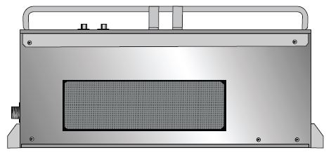
FRONT VIEW