Series PFE - P
- 4kV @ 1.5A and 6kV @ 1A systems
- Can be Used as an Emergency or Auxiliary PFE
- Up and Down Ramp Rates for Voltage and Current
- Push-button Electronic Polarity Setting
- Alarm and Trip Functions
- SMT Option Offers Touch Screen Control, Programmable Electroding Function and Data/Event Logging
*Note: All specifications are subject to change without notice. Please consult the English PDF version of this datasheet for the most up-to-date revision.

High Voltage Power Feed Equipment (PFE)
Spellman's shipborne and land-based power feed equipment (PFE) is used to power submarine fiberoptic cable repeaters for telecommunications shore stations and during cable laying and repair operations. We are the leading supplier of Power Feed Equipment to the Submarine Telecom Industry.
Spellman's Portable PFE (PFE-P) provides the consistent, reliable and safe high voltage power in a compact footprint. The PFE-P incorporates the same advanced digital management system as Spellman's Shipborne PFE (PFE-SB); including voltage and current control, push-button polarity setting, continuous monitoring and alarm reporting from the Main Control Unit (MCU).
The system can be configured with the optional System Management Terminal (SMT) to provide programmable electroding functions, data and event logging and fully adjustable ramp rates, trips and alarms.
The system is powered from a 230Vac single phase mains supply.
(Ref. PFE REV. A)
SPECIFICATIONS
Input Voltage:
230Vac ±10% 50/60Hz (Single Phase)
Input Current:
50A ac maximum at minimum line voltage
Output Voltage:
0 to 6kV, linearly controllable via the MCU
Output Current:
1A maximum at any output voltage up to 6kV
Polarity:
Reversible by selecting positive or negative mode on the MCU when the HV is disabled.
Voltage and Current Ramp Rates:
See MCU and SMT description.
Voltage Ripple:
<0.1% pk-pk of max output +1Vrms
Stability:
Typically <0.25% over any 24 hour period with a temperature range of 0°C to 30°C.
Voltage Regulation:
Load: 0.05% of full voltage +500mV for full load change
Line: +/-0.05% of full voltage +500mV over specified range
Current Regulation:
Load: 0.05% of full current for any voltage change
Line: +/-0.05% of full current over specified input range
Temperature Coefficient:
< 100 ppm/°C
Operating Temperature:
0 to +30°C
Humidity:
0% to 90%, non-condensing
Cooling:
Local cooling and/or ventilation needs to be adequate to balance the system heat dissipation of 1.2kW at 6kV, 1A output.
Safety:
The MCU is equipped with an Emergency Stop Button. Terminals in the rear of the cabinet allow connection of external emergency stop devices.
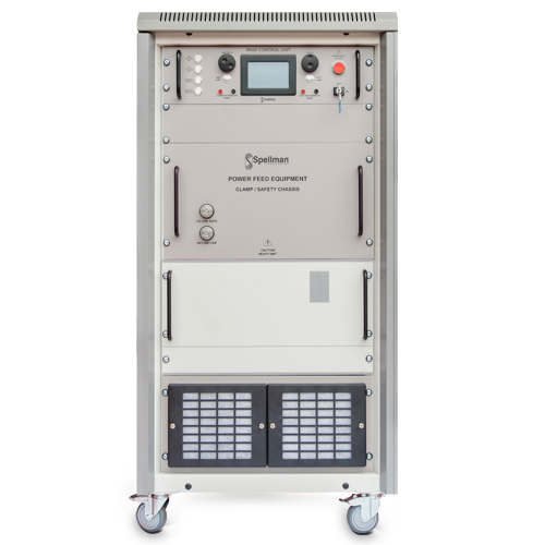
Clamp/Safety Chassis:
Protects the connected line and PFE-P. A HV dump circuit will quickly and safely discharge the system in the event of emergency shutdown Front panel mounted lamps indicate if the PFE-P output is safe or energized.
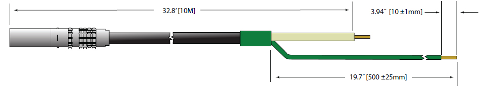
HV Output:
The unit is supplied with 10 meters of RG213/URM67 cable terminated with a 15kV Lemo plug. See HV Output cable detail dwg.
Control:
Manual controls for output voltage and current are provided on the MCU front panel. The PFE-P is capable of operating in either Constant Current or Constant Voltage mode as required by the operator.
Protection:
Over-voltage and Over-current protection levels are settable on the MCU. In the event of a cooling fan failure, the internal temperature limit ensures a safe system shutdown.
Regulatory Approvals:
RoHS compliant. Designed to meet IEC/UL 61010-1 safety requirements for electrical equipment for measurement, control and laboratory use; CAN/CSA-C22.2 No.61010-1.
사양
Main Control Unit (MCU):
The system can be controlled manually using the MCU front panel controls.
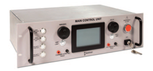
- 4.2” LCD display
- Full output control and monitoring including polarity reversal
- 4mm socket monitor points for voltage and current
- Front panel controls for voltage and current
- Ramp rates available:
Default: 60kV/min 6A/min
Slow: 500V/min 0.2A/min - Over volts/current trips
- HV ON and Alarm outputs provided for customer installation of warning lights and alarms
Interlock System:
Full protection for user and connected equipment. All PFE-P access panels and patch panel connections are interlocked. External connection terminals are provided to allow connection to CTCs, associated equipment or external E-Stop devices.
OPTIONS
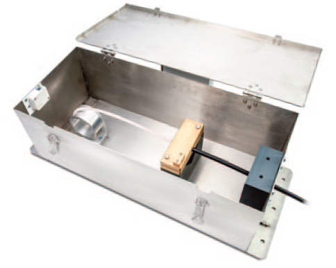
Cable Termination Cubicle (CTC12/377)
Facility to safely accommodate half joints and bare cables for installation and repairs. The CTC provides a safe, interlocked enclosure for connection of the PFE HV to the cable conductors. 2 clamps and strain relief allow the fiber core to be separated and safely routed out of the box to external optical equipment.
W 27.26˝ [692mm]
D 10.44˝ [265mm]
H 8.27˝ [210mm
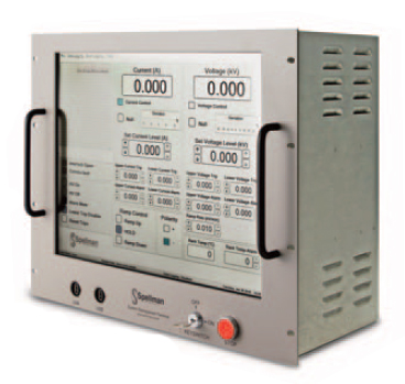
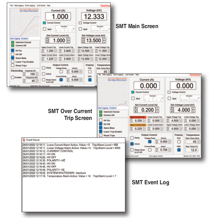
System Management Terminal (SMT):
The optional SMT is an advanced touchscreen control and monitoring system which can be installed on top of the PFE or remotely up to 80m from the PFE.
- Full output control and monitoring
- Fully adjustable ramp rates in current or voltage control: 10V-10kV/min and 10mA-10A/min
- User settable over/under voltage and current trips and alarms
- Output voltage and current logging
- Event logging
- Programmable electroding (tone generator 10-40Hz provided)
Typical System Management Screens:
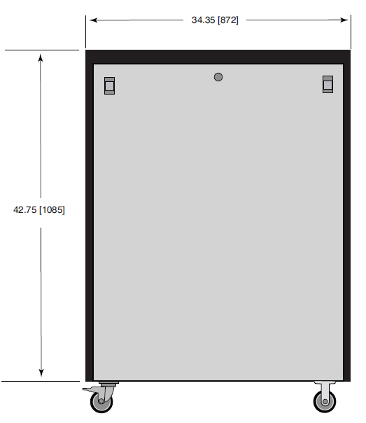
DIMENSIONS: in.[mm]
FRONT VIEW
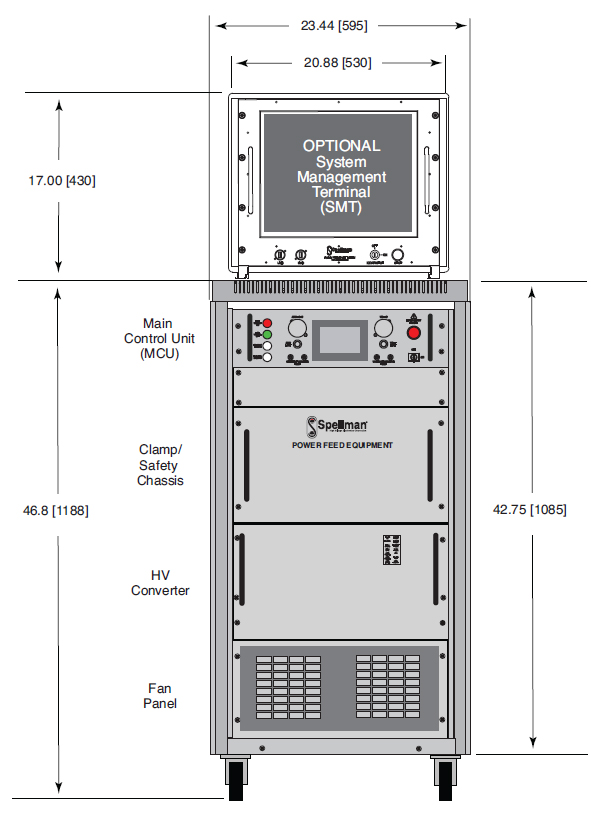
PFE-P Weight Optional SMT 33lbs. [15kg] PFE-P 298lbs. [135kg]
SIDE VIEW
HV Output Cable
The unit is supplied with 10 meters of RG213/URM67 cable. Assembly terminated with a 15kV Lemo plug.