")
SERIE XRB80PN100HR
- Suministro integrado de alto voltaje, suministro de filamento, tubo de rayos X, puerto de haz y electrónica de control
- Compacto y ligero
- Entrada universal, factor de potencia corregido con filtro EMI interno
- Se puede montar en cualquier orientación física
- Interfaz de monitoreo analógico e interfaz digital estándar de programa y monitor RS-232
- Data Logging and Firmware Controlled X-Ray Tube Seasoning (Smart Controller Option Only)


FUENTE INTEGRADA DE RAYOS X DE 80 KV, 100 W
El generador de Rayos X XRB80PN100HR (alta confiabilidad) de Spellman® está diseñado para aplicaciones OEM que alimentan su tubo interno bipolar de rayos X de hasta 80 kV a 100 W. Características como la entrada universal, el tamaño pequeño y una interfaz RS-232 digital estándar simplifican la integración de este Monoblock® en su sistema de rayos X. El XRB80PN100HR está disponible con geometrías de haz en forma de abanico (estándar) o (opcional) cono. Los circuitos patentados de control de emisiones proporcionan una excelente regulación de la corriente del tubo de rayos X, junto con un rendimiento de estabilidad excepcional. El XRB80PN100HR está diseñado para una larga vida útil en el campo. The XRB80PN100HR is designed for long field life and comes with a 3 year warranty.
Aplicaciones típicas:
- Barrido de rayos X
- Medición de espesores
- Inspección de alimentos
- Confirmación de nivel de llenado
- Inspección de paquetería
Especificaciones
(Ref. 128118-001 REV. N)
X-Ray Characteristics:
Focal Spot:
0.8mm (IEC 336) standard
0.5mm (IEC 336) optional
Beam Filter:
Ultem: 3.00mm ±0.15mm
Oil: 7.5mm ±0.25mm
Glass: 1.7mm ±0.2mm
Be: 0.8mm
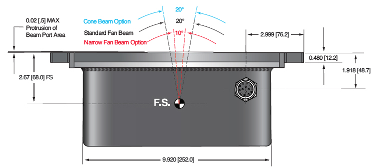
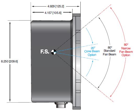
Beam Geometry:
Fan: Standard. The beam angular coverage will be 80° with the beam plane perpendicular to the X-Ray tube axis and 20° wide (with a 2° tolerance)
Cone: Optional. 20° cone beam (with a 2° tolerance)
Input Voltage:
Power factor corrected input 0.98, 100-240Vac ±10% 50/60Hz, 2A maximum
X-Ray Tube Voltage:
Nominal X-Ray tube voltage is adjustable 40kV (±20kV) to 80kV (±40kV)
X-Ray Tube Current:
150uA to 2.00mA over specified tube voltage range (100W max.)
X-Ray Tube Power:
100W, maximum continuous
Voltage Regulation:
Line: ±0.05% of maximum output voltage over a ±10% change of nominal input line voltage
Load: ±0.1% of maximum rated voltage for 150uA to 2.00mA load change
Voltage Accuracy:
Voltage measured across the X-Ray tube is within ±2% of the programmed value
Voltage Risetime:
Standard: Ramp time shall be <500ms from 10% to 90% of maximum rated output voltage
Voltage Ripple:
0.5% peak to peak of maximum voltage for frequencies ≤1kHz
Emission Current Parameters
Current Regulation:
Line: ±0.05% of rated output current over a ±10% change of nominal input line voltage
Load: ±0.1% of rated output current for a change from 50% to 100% of rated output voltage
Current Accuracy:
Current measured through the X-Ray tube is within ±2% of the programmed value
Current Risetime:
Standard: Ramp time shall be <500ms from 10% to 90% of maximum rated current
Arc Intervention:
4 arcs in 10 seconds with a 100ms quench/100ms re-ramp = Shutdown
Filament Configuration:
Internal AC filament drive with closed loop filament emission control
Analog Monitoring Interface:
Ground referenced 0 to 9Vdc for all monitoring signals.
Relay contacts and open collector signals for other signals. See analog interface connector pin out table.
Digital Programming and Monitoring Interface:
The RS-232 interface allows for programming of kV, mA output and X-Ray enable. Provides monitoring for kV, mA output and oil temperature. Tolerance 3%. (with an additional 5μA offset at ≤10% mA programming)
Control Software:
A demo GUI is available for engineering evaluations
Operating Temperature:
0°C to +40°C
Storage Temperature:
-40°C to +70°C
Humidity:
10% to 95% relative humidity, non-condensing
Cooling:
X-Ray Tank: Customer provided 250 cfm external cooling fan as required to maintain oil temperature below 55°C.
Controller: Forced air via internal fan.
Input Line Connector:
3-pin Phoenix Contact 1829167. Mating connector provided with unit
Analog Interface Connector:
15 pin Male D connector provided with unit
Digital Interface Connector:
9 pin female D connector, female
Grounding Point:
M4 ground stud provided on chassis
Dimensions:
X-Ray Tank: 11.3˝L X 9.625˝W X 4.93˝H (287.02mm x 244.4mm x 125.2mm
Controller: 8.5˝L X 6.70˝W X 2.21˝H (215.9mm x 170.2mm x 56.1mm)
Weight:
X-Ray Tank: 36lbs (16.32kg)
Controller: 3.7lbs (1.68kg)
Orientation:
Can be mounted in any orientation.
X-Ray Leakage:
Not to be greater than 0.5mR/hr at 5cm outside the external surface.
Regulatory Approvals:
Compliant to EEC EMC Directive. Compliant to EEC Low Voltage Directive. UL/CUL recognized file E235530
Options:
CB Cone Beam
.5mm .5mm focal spot X-Ray tube
NF 80° x 10° Narrow Fan beam
RA Right Angle cable
SC Smart Controller
AC LINE POWER CONNECTOR— J1 THREE POSITION PHOENIX CONTACT
| Pin | Signal |
|---|---|
| 1 | Earth Ground |
| 2 | Line |
| 3 | Neutral |
Mating connector provided with unit
RS-232 DIGITAL INTERFACE— J3 9 PIN FEMALE D CONNECTOR
| Pin | Signal | Parameters |
|---|---|---|
| 1 | N/C | No Connection |
| 2 | TD | Transmit Data |
| 3 | RD | Receive Data |
| 4 | N/C | No Connection |
| 5 | SGND | Signal Ground |
| 6 | NC | No Connection |
| 7 | NC | No Connection |
| 8 | NC | No Connection |
| 9 | NC | No Connection |
XRB80HR ANALOG INTERFACE— J2 15 PIN MALE D CONNECTOR
| Pin | Signal | Parameters |
|---|---|---|
| 1 | Power Supply Fault Output | Open collector, 35V @ 10mA max. high = no fault |
| 2 | N/C | No Connection |
| 3 | N/C | No Connection |
| 4 | X-Ray On Lamp Relay Output | Common, dry contacts, 30Vdc @ 1A, max |
| 5 | X-Ray On Lamp Relay Output | Normally open, X-Ray ON = closed |
| 6 | mA Monitor Output | 0 to 9Vdc = 0 to 100% rated output, Zout =10kΩ |
| 7 | X-Ray On Lamp Relay Output | Normally closed, X-Ray ON = open |
| 8 | kV Monitor Output | 0 to 9.00Vdc = 0 to 100% rated output, Zout =10kΩ |
| 9 | Signal Ground | Ground |
| 10 | Signal Ground | Ground |
| 11 | HV Interlock Return Input | Connect to Pin 12 to close HV interlock |
| 12 | HV Interlock Output | +15Vdc @ open, 5mA when connected to pin 11 |
| 13 | X-Ray Enable Output | +15Vdc @ open, 5mA when connected to pin 15 |
| 14 | X-Ray Status Output | Open collector, 35V @ 10mA max high = X-Ray OFF |
| 15 | X-Ray Enable Return Input | Connect to pin 13 to enable X-Ray generation (for local enable) |
LED INDICATORS
| Indicator | Signal Name | Condition Illuminated When... |
|---|---|---|
| LED 1 | OV | High kV occurs |
| LED 2 | UV | Low kV occurs |
| LED 3 | UC | Low mA occurs |
| LED 4 | OC | High mA occurs |
| LED 5 | ARC FLT | Arc fault occurs |
| LED 6 | OT | Over temperature occurs |
| LED 7 | X-RAY ON | X-Rays are enabled |
| LED 8 | PWR | Power is ON |
| How to Order: |
|---|
| Standard: Part No.: XRB80PN100HR |
|
Cone Beam Option Part NO.: XRB80PN100HR/CB |
|
0.5mm Focal Spot Option Part NO.: XRB80PN100HR/.5mm |
|
80° X 10° Narrow Fan Beam Option Part NO.: XRB80PN100HR/NF |
|
Cable Option: Part NO.: XRB*)PN100HR/RA |
|
Smart Controller Option Part NO.: XRB80PN100HR/SC |
| SMART XRB (only available with Smart Controller option) |
|---|
|
The XRB80PN100HR with the Smart Controller (SC option) has two new digital features available: data logging and firmware controlled seasoning. Data Logging: FAULT EVENTS The XRB80PN100HR stores data 620ms before the event, the event itself and for 620ms after the event. Data is recorded every 20ms (62 samples total) showing: Anode kV We also log non-fault events, these are changes in set points or state of the unit. NON FAULT EVENTS Fault event data is actual graphical data. Non fault event data is just stored as event type, data and timestamp. We also have a preventative maintenance fault, which throws a non-shutdown alarm if the X-Ray tube has been factory installed over 4 years ago or if over 15,000 hours of HV ON is logged. Firmware Controlled Seasoning:
|
Tablas y Diagramas
OPTIONS
CB Cone BEam
.5mm .5mm focal spot X-Ray tube
NF80° x 10° Narrow Fan beam
RA Right Angle cable
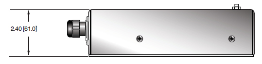
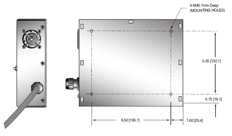
DIMENSIONS: in.[mm]
CONTROL UNIT
TOP VIEW
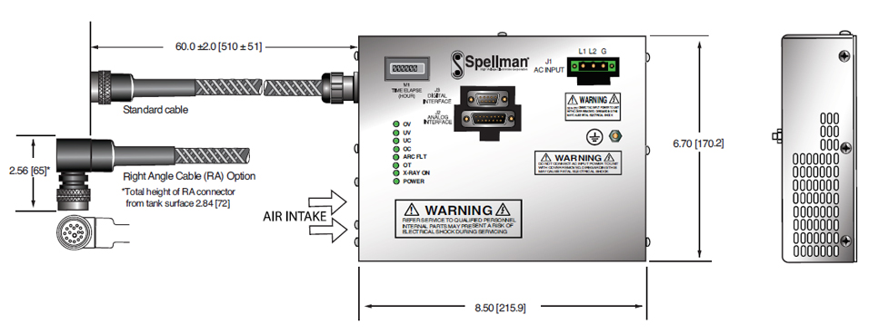
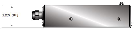
SIDE VIEW
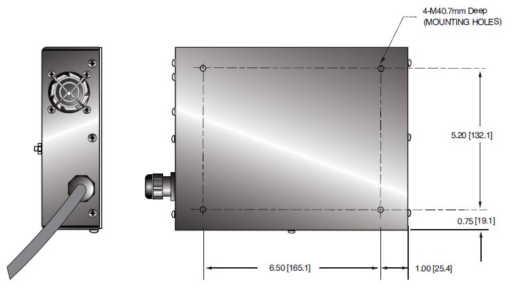
BOTTOM VIEW
DIMENSIONS: in.[mm]
SMART CONTROL UNIT
TOP VIEW
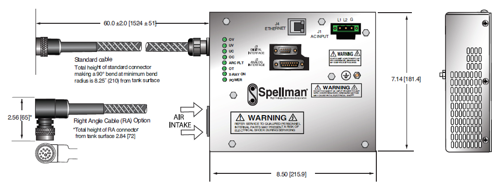
SIDE VIEW
BOTTOM VIEW
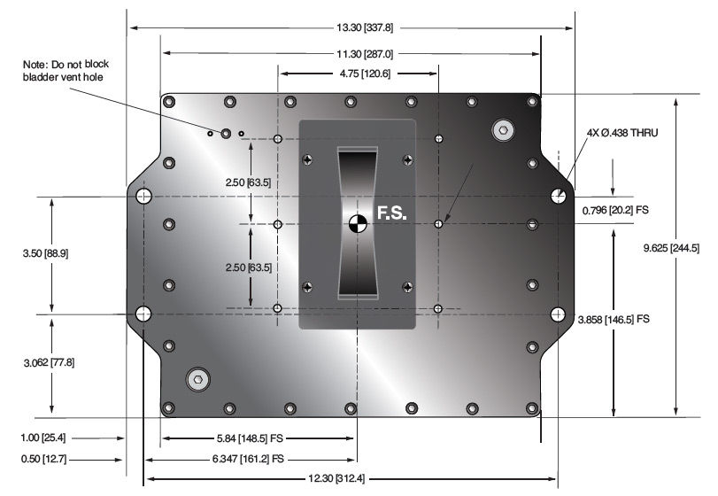
DIMENSIONS: in.[mm]
GENERATOR TANK
TOP VIEW
FRONT VIEW
SIDE VIEW
Frequently Asked Questions
Why Is Oil Insulation Used?
Do I Need to Ensure My Monoblock® Stays Cool? Why?
How Often Do I Need to Season My Monoblock® X-Ray Source? Why?
Application Notes AN-12 – The Benefit of Using a Current Source to Power X-Ray Tube Filament Circuits

