Serie PMX70
- Formato Modular Compacto de Ahorro de Espacio.
- Tiempos rápidos de subida/bajada
- Capacidad de impulso/frenado del arrancador de alta velocidad.
- Ethernet/RS-232 Interfaces
*Nota: Todas las especificaciones pueden cambiar sin previo aviso. Por favor, consulte la versión en PDF en inglés de esta hoja técnica para la revisión más actualizada.


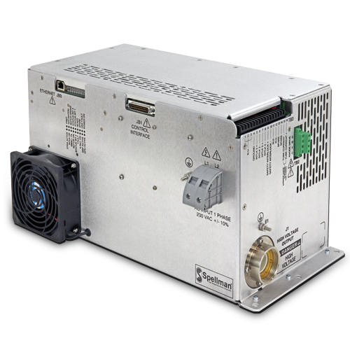
PMX70
La PMX70 es el nuevo generador del alto voltaje de alto rendimiento de Spellman diseñado para alimentar tubos de mamografía Varex y de rayos X. Cuenta con un inversor de alta frecuencia de 12 kW pico y una sección de alto voltaje, con una fuente de alimentación para filamento de aprendizaje inteligente y un arrancador de alta velocidad. La tecnología de conversión de potencia de última generación proporciona un alto voltaje estable y preciso en tubos de rayos X, con tiempos de subida y bajada rápidos. La interfaz Ethernet y RS-232 facilita la integración del sistema. Parámetros precargados del tubo de rayos X, enclavamientos de fácil acceso y conexiones de Entrada/Salida, y diagnósticos internos del generador. También se ofrece un software utilitario opcional de interfaz gráfica para ayudar con la integración inicial del sistema.
Especificaciones
(Ref. 128113-001 REV. A)
Input Voltage:
230Va c ±10%, single phase, 50Hz/60Hz
Input Current:
30 amps, customer to fuse.
Mains Contactor – not provided.
Customer is responsible for mains safety disconnection.
Less than 30 amps over a typical scan is defined as following: Due to unknown line impeadance, customer supllied external inductors 100uH to 300uH in series with input connections, (200uH to 600uH total), may be required to keep rms currents below 30 amps and to avoid erroneous circuit breaker trips. Spellman can recommend appropriate inductors as required.
Output (Tube) Voltage
Output Voltage Range:
25kV to -70kV
Polarity:
Negative output polarity; to drive rotating anode, floating cathode X-Ray tube (Varex M-1581).
Accuracy:
2% (measured per IEC60601-2-45)
Reproductibility:
<0.5%
Output (Tube) Current/Power
Output Current Range:
10mA to 200mA
Output Power:
12kW peak, 400 watt average.
Duty Cycle:
25%. A typical scan being at fixed settings in the range of 40kV- 70kV and 16mA-200mA. Pulsed operation is supported.
Accuracy:
< ±10% on exposure less than 10ms (measured per IEC60601-2-45)
Rise Time:
1-2 milliseconds, typical (HV cable dependent). Fall time is load dependant, and the HV cable is a significant factor. The HV cable which is not provided with the PMX70, has a maximum length of 8 feet (2.4m).
Fall Time:
<10ms with a HV cable length of 8 feet (2.4 meters)
Exposure Time (Loading Time):
Maximum Single Exposure Time:
20 seconds
Shortest Single Exposure Time:
4ms
Loading time accuracy:
±3% +1ms (measured per IEC60601-2-45)
Maximum mAs:
3200mAs
Exposure Timer:
4ms-20 seconds
Reproductibility:
<0.5%
Filament Configuration:
AC high frequency filament drive: self-corrected filament preheat settings with closed loop emission
control and smart learning algorithm.
Filament Output:
0-6 amps at a compliance of 5.5 volts, maximum.
High Speed Starter:
High speed (360Hz) starter configured via the serial interface. Boost and Brake capability provided.
AC Input Connector:
Two position terminal block
System Interface Connector:
25 pin male D connector
Rotor Interface Connector:
Four position terminal block
Tube and Interlock Interface Connector:
16 pin terminal block
High Voltage Connector:
Claymount CA-11 type or equivalent.
Communication Interface Connector:
Ethernet, RJ45 jack
Grounding Point:
M5 ground stud provided on chassis
Environmental:
Temperature Range:
Operating: 10°C to 40°C
Storage: -40°C to 85°C
Humidity:
20% to 85% RH, non-condensing.
Cooling:
Forced air, Internal fan
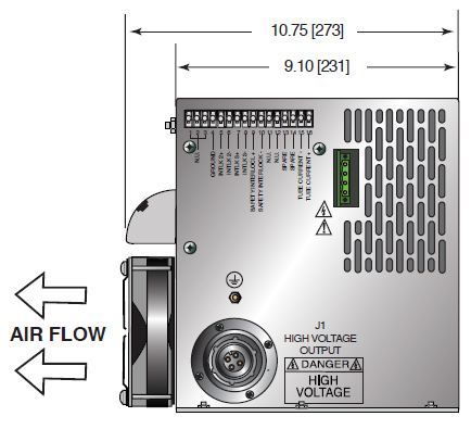
Dimensions:
10.08˝ H X 19.49˝ W X 10.75˝ D (256mm x 495mm x 273mm)
Weight:
48.5 pounds (22.0kg)
Rotational Capability:
Capable of working on a rotating gantry with a nominal rotating speed of 0.5 Hertz.
Regulatory Approvals:
Designed to comply with IEC 60601. RoHS Compliant.
Customer provided external EMC filter may be required to meet CE/EMC specifications.
X-Ray Tube Compatability:
Varex M-1581
PMX70 STANDARD SYSTEM INTERFACE— JB1 25 PIN MALE D CONNECTOR
| Pin | Signal | Parameters |
|---|---|---|
| 1 | GND | Signal Ground |
| 2 | +5Vdc Out | +5Vdc, 100mA max. |
| 3 | RS-232 Tx Out | RS-232 Transmit |
| 4 | RS-232 Rx In | RS-232 Receive |
| 5 | PREP | User signal (Contact Closure) to alert the generator that exposure sequence will begin. Once this signal is active, exposure parameters are locked in and cannot be changed. The generator enables the starter to to boost the rotor. Contact connection to pin 24. Closed = PREP, the filament is placed in preheat mode |
| 6 | READY | Generator signal to user to indicate the rotor runs to speed and the generator is ready for X-Ray exposure Open Collector. Low/Active = Ready |
| 7 | ROTOR SHUTDOWN | User signal to brake the rotor drive |
| 8 | EXPOSURE | User signal (Contact Closure) to generator to generate X-Rays. Filament is boosted, and high voltage is generated after the boost time. Contact connection to pin 24. Closed = Exposure |
| 9 | X-Ray ON 75% Status | Transistor output to indicate X-Ray ON status synchronized with 75% of kVP setting point. |
| 10 | X-Ray ON Status | Transistor output to indicate X-Ray ON status synchronized with kV start up. |
| 11 | N/C | N/C |
| 12 | X-Ray SHUTDOWN/AEC | User signal to generator to rapidly turn HV OFF and ON during serial exposure sequence |
| 13 | RS-232 ISO Ground | Isolated ground from RS-232 transceiver IC |
| 14 | HVG FAULT Status | Generator signal indicating generator fault. Opencollector transistor output. Low/Active = Fault |
| 15 | Status Bit 1 | 3 bit status lines for up to 6 status messages. separate matrix descibing functionality. Open Collector. Low/Active = Message |
| 16 | Status Bit 2 | |
| 17 | Status Bit 3 | |
| 18 | N/C | N/C |
| 19 | N/C | N/C |
| 20 | kV Monitor | Signal from generator. 0-10V = 0-50kV. Zout = 1kΩ |
| 21 | Emission Monitor | Signal from generator. 0-10V = 0-200mA. Zout = 1kΩ |
| 22 | Filament Current Monitor | Signal from generator. 0-10V = 0-6A. Zout = 1kΩ |
| 23 | Program/Monitor Return | Ground for reference of program and monitor signals |
| 24 | +24Vdc Out | For connection to PREP and EXPOSURE control relay coils |
| 25 | SHIELD/GND | For connection of interface cable shield to generator chassis ground |
TB2 ROTOR INTERFACE
| Pin | Signal | Parameters |
|---|---|---|
| TB2-1 | Phase | To tube auxiliary winding |
| TB2-2 | Run | To tube principle winding |
| TB2-3 | Com | To tube common winding |
| TB2-4 | Ground | To tube housing ground |
TB3 TUBE AND INTERLOCK INTERFACE
| Pin | Signal | Parameters |
|---|---|---|
| TB3-1 | SMALL FIL | Connection to tube small filament |
| TB3-2 | COMMON | Connection to tube filament common |
| TB3-3 | LARGE FIL | Connection to large filament |
| TB3-4 | GROUND | Generator chassis for cable shield connection |
| TB3-5 | Interlock 2+ | Used if tube has separate thermostat switch. Open = OVER TEMP. (short terminals if not used) |
| TB3-6 | Interlock 2- | |
| TB3-7 | Interlock 3+ | Used if tube has cooling circulator flow switch. Open = NO FLOW. (short terminals if not used) |
| TB3-8 | Interlock 3- | |
| TB3-9 | Safety Interlock+ | User signal (Contact Closure) for safety interlocks such as door interlocks. Open turns HV OFF, or inhibits HV from being generated. Closed = OK 24Vdc @ <1A typical |
| TB3-10 | Safety Interlock- | |
| TB3-11 | Contactor Coil+ | Option for contactor coil control |
| TB3-12 | Contactor Coil- | |
| TB3-13 | Spare | N/C |
| TB3-14 | Spare | N/C |
| TB3-15 | Tube Current+ | Tube current flows out from this pin |
| TB3-16 | Tube Current- | Tube current flows into this pin |
Tablas y Diagramas
DIMENSIONS: in.[mm]
TOP VIEW

SIDE VIEW
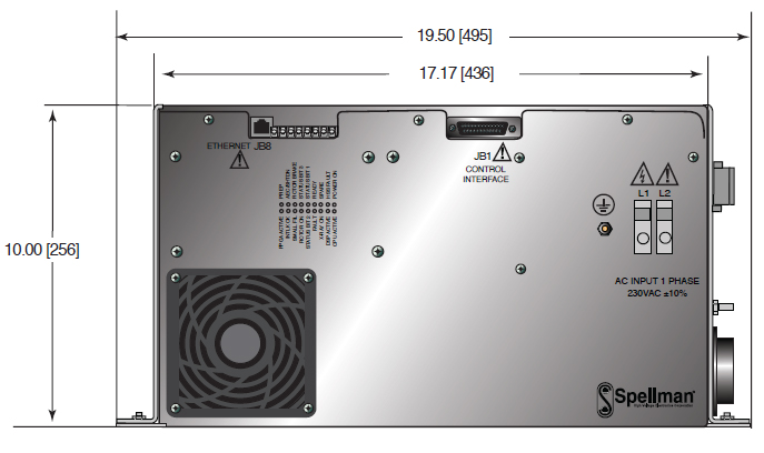
FRONT VIEW
Frequently Asked Questions
Application Notes AN-12 – The Benefit of Using a Current Source to Power X-Ray Tube Filament Circuits
Application Notes AN-01 – Fundamentals of X-Ray Generator – X-Ray Tube Optimization

