UMシリーズ
- 62.5V~6kVの8種類の電圧範囲、固定負極性または正極性
- 4、20、30ワットの出力電力が可能
- 自動クロスオーバー制御による電圧/電流調整
- 電圧および電流モニター信号
- 完全アークおよび短絡保護
- 高精度、5V基準出力
- 包括的な標準インターフェース
- CEリスト、UL認定、RoHS対応
*注: すべての仕様は予告なく変更される場合があります。最新版についてはこのデータシートの英語PDFをご覧ください。

![]()

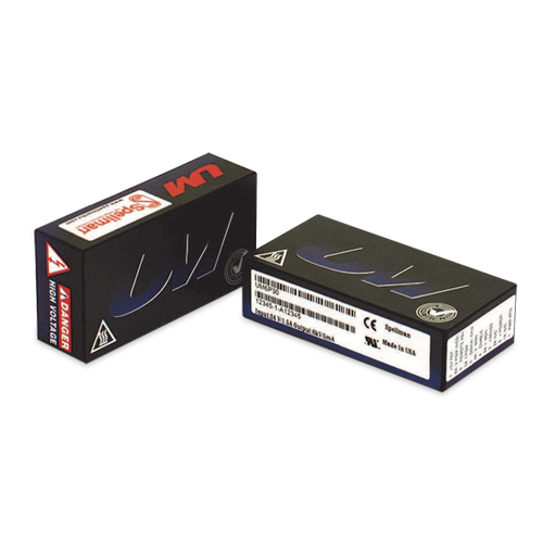
高電圧DC電源
フォーム・フィット・ファンクション設計
UMシリーズは一部の他社製品と取り付け・形状・機能が同等 であるため容易な置き換えが可能です。
また、低価格で追加機能や利便性を提供します。SMT回路を 基盤とするこの高圧モジュールは特許を持つ電力変換技術と60 年以上にわたるスペルマンの高圧製品の経験を駆使して り、性 能と信頼性の向上はもとより、他社の製品と比べて低価格で、し かもシステムへの統合がさらに簡単です。
先進的な電力変換トポロジ
UMコンバータは当社独自開発のゼロ出力電圧スイッチング電 源による電力変換トポロジを使用しているため、これまでにない 効率を提供する一方で、それに うリップルおよびノイズを低減 します。従来のスイッチングトポロジに比べて放射ノイズが少な いため、装置を隣接する電気回路から遮蔽する必要がほとんどな く、場合によっては全く必要あり せん。
フェライトコア使用ステップアップ・トランスフォーマー(ス テップアップ式トランス)を使って高圧出力を発生させます。 1kV以上の装置では、コッククロフト回路を備えた電圧マルチ プライヤステージの半波整流回路を使って、特定の高圧出力を発 生させます。これに対し、低圧装置では、堅牢な整流回路および フィルタ回路が使用されています。
高周波電力変換のスイッチング速度が固定されているため、出 力キャパシタンスが小さく、その結果、蓄積エネルギーが最小限 に抑えられます。定格出力を抑えたサージ保護用抵抗と 速作動 カレントループの使用により、どの装置もアークおよび短絡から 完全に保護されています。
制御とレギュレーション
実際に発生する出力電圧は高インピーダンスのデバイダで抽出 され、電圧フィードバック信号が生成されます。電流フィードバッ ク信号は、電流センス抵抗によって高圧出力回路の低圧側帰路端 に生成されます。この装置は外部モニタリングも兼ねて、この2 つの正確なグランドリファレンス出力電圧フィードバック信号を 使って、正確に制御およびレギュレートされます。
UMシリーズの特異な変換トポロジにより、低インピーダンス 負荷または短絡回路の場合も全電流を印加することが可能です。 標準装置は最大定格出力電流 103%に制限されます。
標準インターフェース
UMシリーズのインターフェースは、電流プログラミング能力 を備え、正極性、バッファ付き低インピーダンスの電圧および電 流モニター信号を生成しま (0〜+4.64 Vdcは0〜定格全出力 と同等)。電圧プログラミング入力信号は0〜+4.64Vdcが0〜 定格出力と等しい場合に提供されます。
この電流プログラミング能力により、電流制限をゼロから最大 出力電流100%の範囲で設定することができます。この特性は 全出力電流より低出力がご希望の場合、例えば高感度負荷 保護 する場合などに有用です。
バッファ付き低インピーダンス電圧および電流モニター信号は、 外部回路を直接駆動することができる一方、負荷効果および引き 揚げ効果を最小限に抑えます。この機能的特性は、信 の質を向 上させると同時に、外部インターフェースを付加する手間とコス トを節減します。
この標準インターフェースは0.1インチ間隔で並ぶ13ピンで 構成されています。
一部他社製品と互換性のある 0.2インチ間隔の7ピンインター フェースをご希望の場合はオプションLをご指定下さい。
装置および環境に関する考慮
UMシリーズは密閉型でプリント基板実装が可能なプラス ティックケース収納式コンバータで、実測サイズでわずか 75.4mm×38.1mm×21.1mmです。どの装置も、エポキシ よりはるか 軽いシリコン主体のポッティング材で密閉されてい ます。モジュールは2本の絶縁された非接地型2 ‐ 56機械ねじ でしっかりとプリント基板に固定されるため、インターフェース ピンへの圧力 軽減されます。取付け板、ブラケットおよびフラ ンジ付き実装部品などのオプションも取り揃えています。
規制認可:2004/108/EC、EMC指令および 2006/95/EC、低電圧指令に準拠、 UL/CUL(File E227588)、2002/95/EC に準拠、RoHS対応
Specifications
(Ref. 128068-001 REV. R)
Input Voltage:
12Vdc for 4W, 24Vdc for 20W and 30W
Nominal Voltage Range:
11Vdc to 30Vdc for 4W, 23Vdc to 30Vdc for 20W and 30W
Input Current: (typical)
Disabled: 30mA
No load: 90mA
Full load:
4 watt units: 0.5A
20 watt units: 1.0A
30 watt units: 1.5A
Efficiency:
80-85%, typical
Voltage Regulation:
Line: <0.01%
Load: <0.01%
Current Regulation:
Line: <0.01%
Load: <0.01%
Stability:
0.01% per 8 hours, 0.02% per day after 30 min. warmup
Accuracy:
2% on all programming and monitoring, except I Sense 10%
Temperature Coefficient: (typical)
Standard: 100ppm/°C Optional: 25ppm/°C (T Option)
Environmental:
Temperature Range:
Operating: 0°C to 65°C case temperature
Storage: -55°C to 85°C, non operational
Humidity:
10% to 90%, non-condensing.
Cooling:
Convection cooled, typical. 30 watt units operating at full power might require additional cooling to maintain case temperature below 65°C. Methods may include: forced air cooling, use of heat sink or metal case, etc. It is the user’s responsibility to maintain the case temperature below 65°C. Damage to the power supply due to inadequate cooling is considered misuse and repairs will not be covered under warranty.
Dimensions:
2.97" L X 1.49" W X 0.81" H (75.2mm X 37.9mm X 20.6mm)
Weight:
4 oz. (113g), typical
UM 4W SELECTION TABLE
| Model Number | Output V | Output Current | Low Freq. Ripple %Vp-p @ 1Hz-1kHz | High Freq. Ripple %Vp-p @ 1kHz-1MHz | Output Capacitance | Arc Limiting Resistanc | I Sense Scaling Full Scale Signal | High Voltage Divider Resistance |
|---|---|---|---|---|---|---|---|---|
| UM0.062*4 | 0 to 62.5V | 64mA | 0.030 | 0.028 | 8.8μF | 1Ω | 1.5V | 0.5MΩ |
| UM0.125*4 | 0 to 125V | 32mA | 0.045 | 0.014 | 8.8μF | 4.4Ω | 2.75V | 0.88MΩ |
| UM0.25*4 | 0 to 250V | 16mA | 0.034 | 0.017 | 2.2μF | 20Ω | 4.9V | 1.50MΩ |
| UM0.5*4 | 0 to 500V | 8mA | 0.036 | 0.040 | 0.8μF | 94Ω | 10.1V | 2.65MΩ |
| UM1*4 | 0 to 1KV | 4mA | 0.025 | 0.015 | 0.2μF | 470Ω | 10.75V | 20MΩ |
| UM2*4 | 0 to 2kV | 2mA | 0.022 | 0.015 | 0.097μF | 1.0KΩ | 10.4V | 30MΩ |
| UM4*4 | 0 to 4kV | 1mA | 0.019 | 0.017 | 0.012μF | 9.4KΩ | 11.1V | 100MΩ |
| UM6*4 | 0 to 6kV | 0.67mA | 0.016 | 0.015 | 0.007μF | 20KΩ | 9.9V | 150MΩ |
UM 20W SELECTION TABLE
| Model Number | Output V | Output Current | Low Freq. Ripple %Vp-p @ 1Hz-1kHz | High Freq. Ripple %Vp-p @ 1kHz-1MHz | Output Capacitance | Arc Limiting Resistance | I Sense Scaling Full Scale Signal | High Voltage Divider Resistance |
|---|---|---|---|---|---|---|---|---|
| UM0.062*20 | 0 to 62.5V | 320mA | 1Hz-1kHz 0.060 | 0.088 | 8.8μF | 1Ω | 330mV | 0.5MΩ |
| UM0.125*20 | 0 to 125V | 160mA | 0.067 | 0.044 | 8.8μF | 4.4Ω | 675mV | 0.88MΩ |
| UM0.25*20 | 0 to 250V | 80mA | 0.035 | 0.019 | 2.2μF | 20Ω | 1.135V | 1.50MΩ |
| UM0.5*20 | 0 to 500V | 40mA | 0.041 | 0.040 | 0.8μF | 94Ω | 2.25V | 2.65MΩ |
| UM1*20 | 0 to 1KV | 20mA | 0.039 | 0.095 | 0.2μF | 470Ω | 4.35V | 20MΩ |
| UM2*20 | 0 to 2kV | 10mA | 0.026 | 0.016 | 0.097μF | 1.0KΩ | 6.6V | 30MΩ |
| UM4*20 | 0 to 4kV | 5mA | 0.023 | 0.028 | 0.012μF | 9.4KΩ | 6.65V | 100MΩ |
| UM6*20 | 0 to 6kV | 3.3mA | 0.017 | 0.018 | 0.007μF | 20KΩ | 6.74V | 150MΩ |
UM 30W SELECTION TABLE
| Model Number | Output V | Output Current | Low Freq. Ripple %Vp-p @ 1Hz-1kHz | High Freq. Ripple %Vp-p @ 1kHz-1MHz | Output Capacitance | Arc Limiting Resistance | I Sense Scaling Full Scale Signal | High Voltage Divider Resistance |
|---|---|---|---|---|---|---|---|---|
| UM0.062*30 | 0 to 62.5V | 480mA | 0.075 | 0.112 | 8.8μF | 1Ω | 500mV | 0.5MΩ |
| UM0.125*30 | 0 to 125V | 240mA | 0.075 | 0.056 | 8.8μF | 4.4Ω | 930mV | 0.88MΩ |
| UM0.25*30 | 0 to 250V | 120mA | 0.055 | 0.031 | 2.2μF | 20Ω | 1.65V | 1.50MΩ |
| UM0.5*30 | 0 to 500V | 60mA | 0.085 | 0.041 | 0.8μF | 94Ω | 3.4V | 2.65MΩ |
| UM1*30 | 0 to 1KV | 30mA | 0.032 | 0.171 | 0.2μF | 220Ω | 6.5V | 20MΩ |
| UM2*30 | 0 to 2kV | 15mA | 0.031 | 0.112 | 0.097μF | 470Ω | 9.85V | 30MΩ |
| UM4*30 | 0 to 4kV | 7.5mA | 0.028 | 0.071 | 0.012μF | 4.4KΩ | 9.85V | 100MΩ |
| UM6*30 | 0 to 6kV | 5mA | 0.020 | 0.051 | 0.007μF | 9.4KΩ | 10.0V | 150MΩ |
Note: Total ripple is the sum of the low frequency and high frequency ripple. Grayed text indicates Legacy interface signals.
STANDARD INTERFACE
| Pin | Signal | Parameters |
|---|---|---|
| 1 | Power Ground Return | +12Vdc or +24Vdc power return/HV return |
| 1A | Signature Resistor | Unique Identifying resistor connected to ground |
| 2 | + Power Input | +12Vdc or +24Vdc power input |
| 2A | N/C | |
| 3 | I Sense | See I Sense text and tables |
| 3A | I Mon | 0 to 4.64Vdc = 0 to 100% rated output. Zout < 10kΩ |
| 4 | Enable Input | Low (<0.7V, Isink@1mA)=HV OFF, High (open or >2V)=HV ON |
| 4A | V Mon | 0 to 4.64Vdc = 0 to 100% rated output. Zout < 10kΩ |
| 5 | Signal Ground | Signal Ground |
| 5A | I Pgm | 0 to 4.64Vdc = 0 to 100% rated output. Zin > 47kΩ Leave open for preset current limit @103% of rated output current |
| 6 | Remote Adjust | Positive Polarity Unit: 0 to +4.64VDC = 0 to 100% rated voltage, Zin >1MΩ Negative Polarity Unit: +5VDC to 0.36V = 0 to 100% rated voltage, Zin >100kΩ Leave open if pin 6A (VPgm) is used for programming |
| 6A | V Pgm | 0 to 4.64Vdc = 0 to 100% rated voltage. Zin > 100kΩ Leave open if pin 6 (remote adjust) is used for programming |
| 7 | +5V Reference Output | +5Vdc ±0.5%, 50ppm/°C. Zout =475Ω |
| 8 | HV Ground Return | HV Ground Return |
| 9 | E Out Monitor | 10:1 ratio for models below 1kV, 100:1 ratio for models 1kV and above. Polarity of Voltage Monitor signal equals polarity of unit. Accuracy is ±2%, 100ppm/°C. Calibrated with DVM with 10MΩ input impedance |
| 10 | HV Output | HV Output |
| 11 | HV Output | HV Output |
Grayed out signals are provided for backward legacy compatibility and their use is not required
Power Ground Return, Signal Ground and HV Ground Return are connected internally. For best performance they should not be connected externally.
LEGACY INTERFACE (L OPTION)
| Pin | Signal | Parameters |
|---|---|---|
| 1 | Power Ground Return | +12Vdc or +24Vdc power return/HV return |
| 2 | + Power Input | +12Vdc or +24Vdc power input |
| 3 | I Sense | See I Sense text and tables for details |
| 4 | Enable Input | Low (<0.7V, Isink@1mA)=HV OFF, High (open or >2V)=HV ON |
| 5 | Signal Ground | Signal Ground |
| 6 | Remote Adjust | Positive Polarity Unit: 0 to +4.64VDC = 0 to 100% rated voltage, Zin >1MΩ Negative Polarity Unit: +5VDC to 0.36V = 0 to 100% rated voltage, Zin >100kΩ |
| 7 | +5V Reference Output | +5Vdc ±0.5%, 50ppm/°C. Zout =475Ω |
| 8 | HV Ground Return | HV Ground Return |
| 9 | E Out Monitor | 10:1 ratio for models below 1kV, 100:1 ratio for models 1kV and above. Polarity of Voltage Monitor signal equals polarity of unit. Accuracy is ±2%, 100ppm/°C. Calibrated with DVM with 10MΩ input impedance |
| 10 | HV Output | HV Output |
| 11 | HV Output | HV Output |
Power Ground Return, Signal Ground and HV Ground Return are connected internally. For best performance they should not be connected externally.
Tables & Diagrams
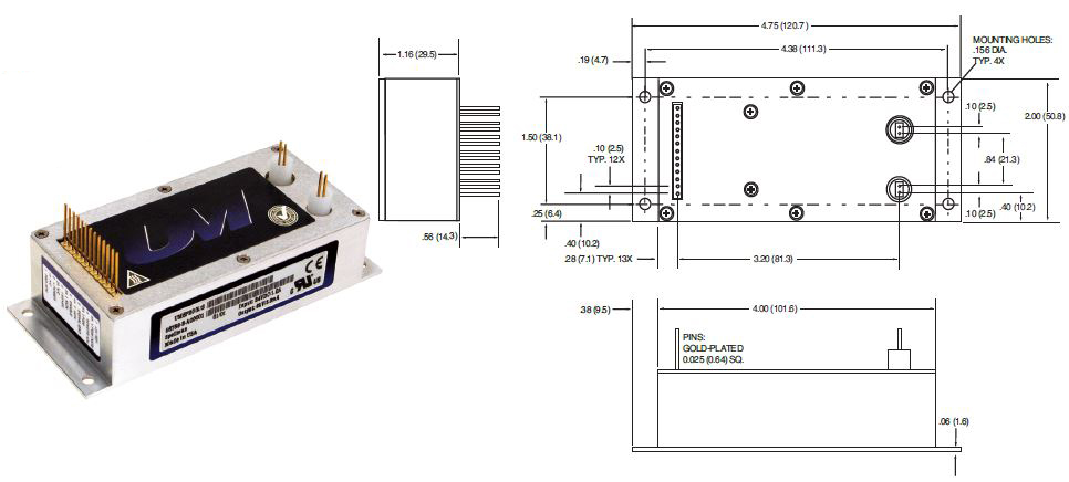
Standard Interface Connections
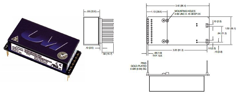
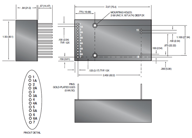
Seventeen (17) gold plated 0.025˝ (0.64mm) square pins suitable for direct PCB mounting. See mechanical drawing for location and spacing details.
Programming and Monitor Signals
Voltage and current programming is done via positive polarity, high input impedance, 0 to 4.64Vdc signals.
Voltage and current monitors are positive polarity, buffered low output impedance 0 to 4.64Vdc signals.
I Mon
The I Mon signal is a true output current monitoring signal. All internal offsets due to feedback divider
currents have been compensated for.
Signature Resistor
A unique identifying signature resistor for each type of unit is connected from Pin 1A to ground. Details if desired are available upon request.
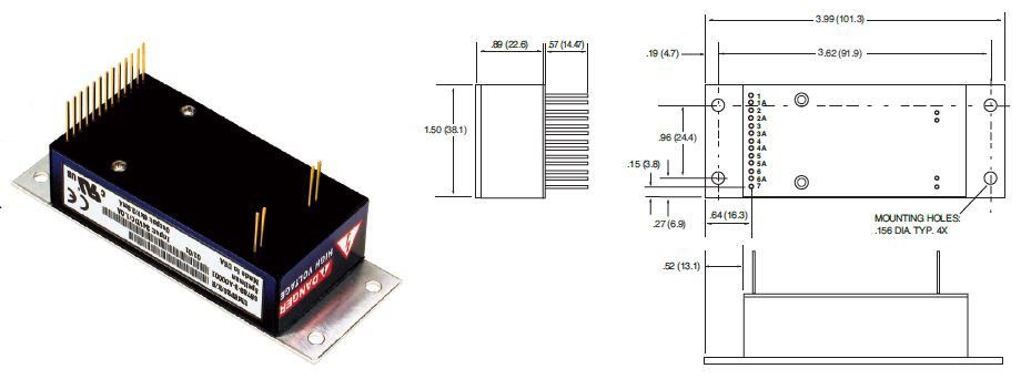
Legacy Interface Connections
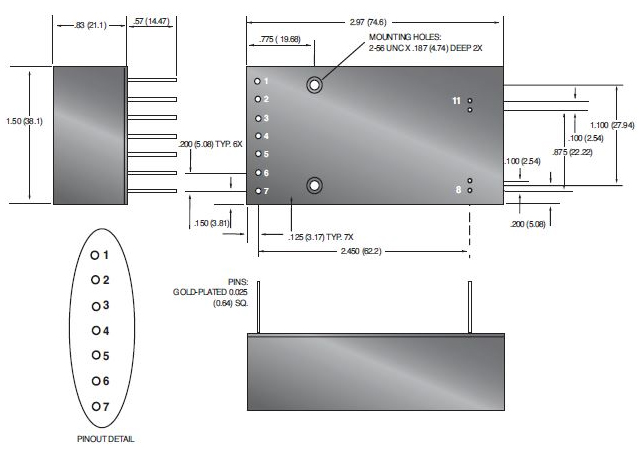
Eleven (11) gold plated 0.025˝ (0.64mm) square pins suitable for direct PCB mounting. See mechanical drawing for location and spacing details.
I Sense Signal
The I Sense signal polarity is opposite of the output polarity of the module. This signal is protected via a transorb and provided via a series connected 47k isolation resistor. Internal HV dividers create a small, linear offset voltage on the I sense signal that can be compensated for.
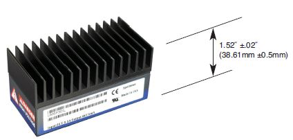
Adhesive Backed Heat Sink
UM modules are provided with an uninstalled top mounted adhesive backed heat sink. Label removal is not required if the customer elects to install and use the provided heat sink.
The UM's internal power dissipation causes a case temperature rise. If the case exceeds 65°C, the unit needs external cooling (fan or heat sink). Even if the case is below 65°C, it is prudent to keep it much lower. Like a semiconductor device; the hotter it is, the shorter the life. For every 10°C reduction of temperature the lifetime will be increased by a factor of ≈2.35. The thermal resistance from internal circuitry to ambient is 8°C/watt without a heat sink (still air). This reduces to 6°C/watt with the heat sink.
Example:
Assuming ≈80% efficiency for a 20 watt UM module, the
5 watts of internal power dissipation would create a 40°C rise. Using the heat sink there would be only a 30°C rise. Ultimately it is up to the user to determine what cooling method is applicable for their application, but the general recommendation is to keep the module as cool as possible.
UM OPTIONS
T Option
Low Temperature Coefficient-
The T Option offers the UM with an improved temperature coefficient. The standard voltage
feedback divider is replaced with one having a superior temperature coefficient, resulting in
a unit with 25ppm/C° (typical) temperature coefficient.
PHYSICAL INTERFACING
A Option
Adapter Board-
Spellman’s UM module can be fitted with an adapter board that will allow a drop in replacement for other commercially available modules of a physically larger size, while providing
identical functionality with superior performance.
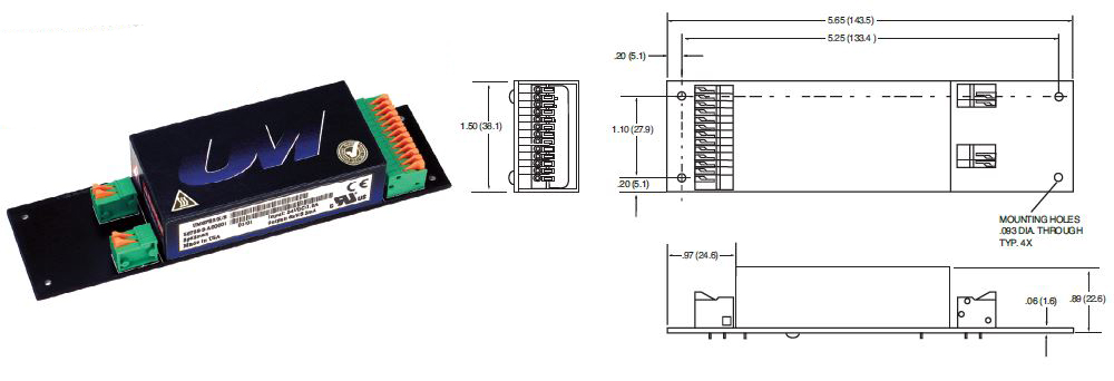
B Option
Terminal Block-
The B Option provides terminal block connections for both the customer interface and high voltage output/return. This feature can be helpful in situations where frequent wiring changes are anticipated, as in a testing or prototype environment.
SHIELDING
M Option
Mu Metal Shield-
UM modules can be fitted with an adhesive backed Mu Metal foil shield to help protect sensitive adjacent circuitry.
Same as standard unit.
S Option
RF Tight Shielded Can-
The S Option mounts the UM module inside of a flanged RF tight aluminum can.
CHASSIS MOUNTING
E Option
Eared Mounting Plate-
An eared mounting plate is affixed to the top surface of the UM module allowing simple chassis mounting of unit.
E2 Option
Eared Mounting Plate-
An eared mounting plate is affixed to the top surface of the UM module allowing simple chassis mounting of units ordered with the Adapter Board (A Option).
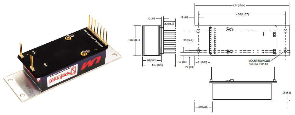
DIMENSIONS: in.[mm]
17 PIN - Standard Interface
11 PIN - Standard Interface
Note: There may be some restrictions on multiple option combinations. Please contact our sales department for more details.
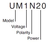
ORDERING INFORMATION
| Voltage | 0 to 62.5Vdc | 0.062 |
| Voltage |
0 to 125Vdc | 0.125 |
| Voltage |
0 to 250Vdc | 0.25 |
| Voltage |
0 to 500Vdc | 0.5 |
| Voltage |
0 to 1000dc | 1 |
| Voltage |
0 to 2000dc | 2 |
| Voltage |
0 to 4000dc | 4 |
| Voltage |
0 to 6000dc | 6 |
| Polarity | Positive | P |
| Polarity | Negative | N |
| Power | Watts Output | 4 |
| Power | Watts Output | 20 |
| Power | Watts Output | 30 |
STANDARD UNIT ORDERING EXAMPLE
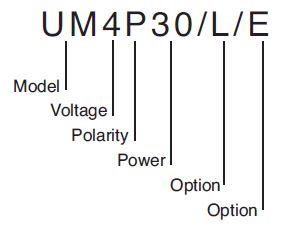
OPTION ORDERING INFORMATION
| OPTION | OPTION CODE |
|---|---|
| Legacy Interface | L |
| Low Temperature Coefficient |
T |
| Adapter Board |
A |
| Terminal Block |
B |
| Mu Metal Shield |
M |
| RF Tight Shielded Can |
S |
| Eared Mounting Plate |
E |
| Eared Mounting Plate/Adapter Board |
E2 |
OPTION ORDERING EXAMPLE
Frequently Asked Questions
What Is a Safe Level of High Voltage?
Where Can I Obtain Information on High Voltage Safety Practices?
How Should I Ground Your Supply?
Why Is Arcing an Issue for a High Voltage Power Supply?

