MSAシリーズ
- コンパクトな高性能モジュール
- 可変電圧プログラミング
- 0.9ワットの出力電力
- 電圧モニター
- アークおよび短絡保護
*注意:すべての仕様は予告なく変更されることがあります。 最新の改訂版については、このデータシートの 英語版PDFを参照してください。

MSA
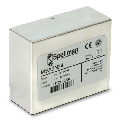
MSAシリーズは、コンパクトなプリント基板実装可能(PCB)高圧電源モジュールで、1kVから3kV、そして正または負の出力極性がございます。またMSAシリーズは、定格出力電圧の0〜100%に相当する0〜10Vdcの可変電圧プログラミングを備えています。0-10Vdcが定格出力電圧の0-100%に等しい電圧モニターが提供されます。さらに、ステータス信号とイネーブル信号により、電源を簡単に制御できます。すべてのユニットには、障害状態に対する保護が組み込まれています。
MSAシリーズは、質量分析計の電子増倍管の駆動など、コンパクトで高性能なPCBにマウント可能な電源が必要な一般的な使用を目的としています。アルミニウム製の筐体はユニットのシールドに役立ち、放射ノイズを低減します。
代表的なアプリケーション
- 光電子増倍管
- 電子増倍管
- 質量分析
- 静電レンズ
- 原子力機器
Specifications
(Ref. 128018-001 REV. D)
SPECIFICATIONS
Input Voltage:
+24 Vdc, ±2Vdc
Input Current:
150mA maximum input current
30mA pk-pk maximum input current ripple
Output Polarity:
Positive or negative, specify at time of order
Output Power:
0.9 watts, maximum
Output Voltage Accuracy:
±1%
Voltage Regulation:
Line: 21.6Vdc to 26.4Vdc, ±0.02%
Load: 0-100% rated load, ±0.02%
Stability: 50ppm/8hrs after one hour warm up period
Temperature Coefficient:
25ppm per degree C
Settling Time: After Power On or Enable
100 milliseconds, typical
When power is removed the unit will decay to <±60 volts within 2 seconds
Protection:
Arc and short circuit protected.
Not designed to withstand continuous arcing
Environmental:
Temperature Range:
Operating: 0˚C to 60˚C
Storage: -20˚C to 70˚C
Humidity:
95% RH, non-condensing
Cooling: Convection cooled
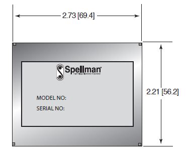
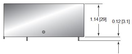
Dimensions:
2.73˝ L x 2.21˝ W x 1.21˝ D (69.4mm x 56.2mm x 30.7mm)
Weight:
7.0 oz. (200g)
Regulatory Approvals:
Designed to meet EN 61010-1, UL 61010A-1 and CAN/CSA-22.2 No. 61010.1 As the unit is intended for incorporation into end users equipment it will not be tested as a standalone unit to meet the EMC directive. The user will need to follow sensible EMC precautions in using the unit. The unit is compliant with the EU RoHS directive
MSA SELECTION TABLE
| Model | Output Voltage | Output Current | Ripple (Vpp) |
|---|---|---|---|
| MSA1*24 | 0-1kV | 0-900μA | 30mV |
| MSA2*24 | 0-2kV | 0-450μA | 40mV |
| MSA3*24 | 0-3kV | 0-300μA | 50mV |
1) Replace the * with “P” for positive output polarity and “N” for negative output polarity.
2) The ripple figure includes random non switch related noise, noise related to the oscillator, switching and feedback control circuitry and noise associated with the rectified primary switching frequency.
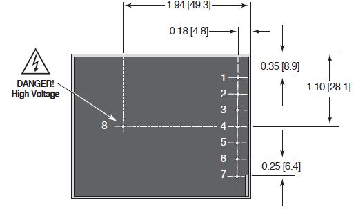
LOW VOLTAGE SIGNAL PINS FOR POWER AND CONTROL
| PIN | SIGNAL | LEVEL | SIGNAL PARAMETERS |
|---|---|---|---|
| 1 | Enable | TTL | Enable = Low (≤1.2V). Disable = High (≥2.4V), when Enable pin is NC, 10kΩ pull up to +5V ±10% |
| 2 | Status | 0V/5V | OK = 11kΩ pull up to +5.1V ±10%. Fault = ≤0.1V, Zout = 1kΩ |
| 3 | Voltage Program | 0-10V | 0 to +10Vdc = 0 to 100% rated output voltage, Accuracy ≈ ±1%. Zin = 10kΩ |
| 4 | Voltage Monitor | 0-10V | 0 to +10Vdc = 0 to 100% rated output voltage, Accuracy = ±2%. Zout = 20kΩ |
| 5 | Input Voltage | 24Vdc | Power Input |
| 6* | Signal Ground | 0V | Ground reference for control and monitoring signals |
| 7* | Power Ground | 0V | Power Return |
To reset the unit after a fault condition, Pin1 (Enable) must be set high for at least 10 seconds
* pins 6 & 7 are linked internally
HIGH VOLTAGE CONNECTION DETAIL
| PIN | SIGNAL | SIGNAL PARAMETERS |
|---|---|---|
| 8 | High Voltage Output | 0-100% Rated Output. !!Danger: High Voltage!! |
Tables & Diagrams
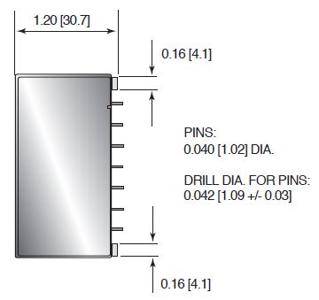
DIMENSIONS: in.[mm]
TOP VIEW
FRONT VIEW
BOTTOM VIEW
SIDE VIEW
Frequently Asked Questions
What Is a Safe Level of High Voltage?
Where Can I Obtain Information on High Voltage Safety Practices?
How Should I Ground Your Supply?
Why Is Arcing an Issue for a High Voltage Power Supply?
