XRB180PN200
- 180kV y 200W
- Corriente de Tubo de rayos X: 0.5mA a 1.1mA
- Punto focal 0.8 x 0.8mm nominal (IEC60336)
- Entrada corregida del factor de potencia a 0.98
- 100Vac a 240Vac, ±10%
*Nota: Todas las especificaciones están sujetas a cambios sin previo aviso. Consulte la versión PDF en inglés de esta hoja de datos para obtener la revisión más actualizada.
XRB180PN200
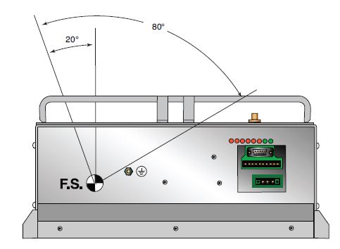
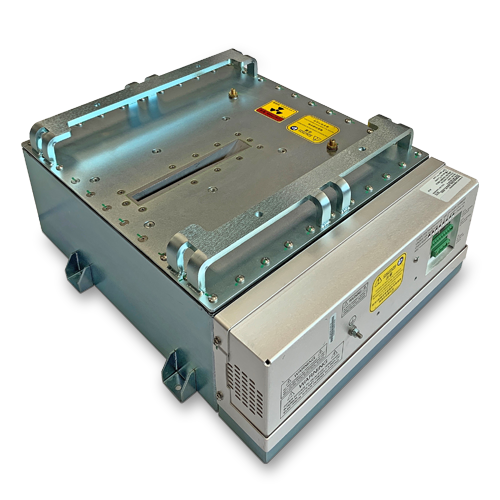
El XRB180PN200 de Spellman es una fuente de rayos X integrada que opera hasta 180kV y 200W, proporcionando a los usuarios OEM un Monoblock compacto plug-and-play para aplicaciones críticas de inspección y cribado. La unidad incorpora un tubo de rayos X de ánodo estacionario de ángulo de 25° que ofrece un haz de ventilador de 80°x 4°. Los circuitos de control de emisiones patentados proporcionan una excelente regulación de la corriente del tubo de rayos X, con una estabilidad de dosis y calidad de imagen líderes en la industria. Este modelo compacto viene con control analógico estándar y digital RS-232. Spellman puede proporcionar versiones personalizadas de esta plataforma para requisitos específicos del sistema OEM. APLICACIONES TÍPICAS Control de seguridad de la aviación: equipaje registrado/EDS, inspección de vehículos en puntos de control, Pruebas No Destructivas general, inspección de alimentos.
TYPICAL APPLICATIONS
Aviation Security Screening: Checked Baggage/EDS, Checkpoint Vehicle Inspection, General NDT, Food Inspection
Especificaciones
(Ref. 128085-001 REV. A)
X-Ray Characteristics:
Tube Type: Stationary Anode, tungsten target
Focal Spot: 0.8 x 0.8mm nominal (IEC60336)
Beam Filter: Consists of oil and the curved Ultem 0.079'' +/-0.01''. Inherent filtration in the X-Ray Tube is 1mm Be, 1.5mm +/-10% glass.
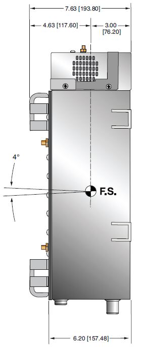
Beam Geometry: Fan of 80° X 4°, ±1%
Anode Angle: 25°
Input Voltage:
Power factor corrected input to 0.98. 100Vac to 240Vac, ±10%, 50/60 Hertz. 5A, maximum
X-Ray Tube Voltage:
Nominal X-Ray tube voltage is adjustable between 90kV to 180kV.
Voltage Accuracy:
The high voltage measured at the X-ray tube will be within ±1% of the selected value.
Voltage Ripple:
Ripple will be ≤0.2% of maximum rated voltage for frequencies ≤1kHz
Voltage Regulation:
< ±0.1% for ±10% of nominal input line change
< ±0.1% for 0.5mA to 1.11mA load change
Voltage Overshoot:
kV overshoot will return within 5% of full voltage in less than 10ms
Risetime:
The voltage and current risetime is controlled by a ramping circuit. Ramp time is less than 0.5 second from 10% to 90% of output voltage and current.
X-Ray Tube Current:
0.5mA to 1.1mA @ 180kV, 200 Watts maximum
Current Accuracy:
<±1% of the selected value.
Current Regulation:
<0.5% at 90-180kV, 0.5mA to 1.1mA
Arc Intervention:
Unit will detect a single arc but HV will not shut down. If multiple arcs occur (4 in 10 seconds) then the unit will shut down.
Filament Configuration:
Internal high frequency AC filament drive operated in current mode with closed loop filament emission control.
Analog Interface:
Ground referenced 0 to 10Vdc for all monitoring signals. Relay contacts and open collector outputs for other signals.
Digital Interface:
Internal high frequency AC filament drive with closed loop filament emission control
Digital Interface:
The RS-232 interface allows for programming of the voltage, current, and X-Ray Enable. Provides monitoring for voltage, current and oil temperature. Tolerance is 3% (with additional 5uA offset at ≤10%mA programming)
Control Software:
A demo GUI is available for engineering evaluation
Operating Temperature:
0°C to +40°C
Storage Temperature:
-40°C to +70°C
Humidity:
10% to 95% relative humidity, non-condensing.
Cooling:
Via natural convection/external cooling fans of 100CFM minimum or maintaining tank/oil temperature below 55°C
Input Line Connector:
3 pin Phoenix Contact, p/n 1829167. Mating connector provided with unit.
Analog Interface Connector:
10 pin Phoenix Contact, p/n 1755503. Mating connector provided with unit.
Digital Interface Connector:
9 pin female D connector. Mating connector provided with unit.
Grounding Point:
M4 grounding stud provided on chassis.
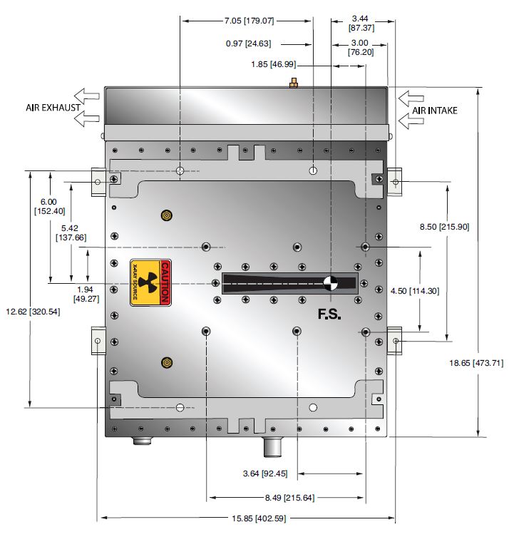
Dimensions:
See outline drawing.
Weight:
132 pounds (60kg).
Orientation:
Can be mounted in any orientation.
X-Ray Leakage:
Not to be greater than .5mR/hr at 5cm from any surface of the Monoblock® when measured at 180kV @ 1.1mA
Regulatory Approvals:
Compliant to EEC EMC Directive. Compliant to EEC Low Voltage Directive.
AC INPUT POWER 3 PIN P/N 1829167
| Pin | Signal | Parameters |
|---|---|---|
| 1 | Line | 100-240Vac,±10%, 50/60 Hertz @ 6 amps |
| 2 | GND | Ground |
| 3 | Neutral | 100-240Vac,±10%, 50/60 Hertz @ 6 amps |
ANALOG INTERFACE— 10 PIN PHOENIX CONTACT P/N 1755503
| Pin | Signal | Parameters |
|---|---|---|
| 1 | X-Ray On | +24Vdc = Enable X-Ray, Low or open = Disable X-Ray |
| 2 | X-Ray On Return | X-Ray on Return |
| 3 | N/C | No Connection |
| 4 | RTN | 0 to 10Vdc = 0 to 200kV, Zout = 10kΩ |
| 5 | kV Monitor | Signal Ground |
| 6 | SGND | 0 to 10Vdc = 0 to 1.5mA, Zout = 10kΩ |
| 7 | Fault | Open Collector, High (Open) = No Fault, 35Vdc @ 10mA, maximum |
| 8 | HV On Lamp N/O | Relay dry contact, normally open, 30Vdc @ <1A, nominal 50mA DC load |
| 9 | HV On Lamp Common | Relay dry contact, common, 30Vdc @ <1A, nominal 50mA DC load |
| 10 | HV On Lamp N/C | Relay dry contact, normally closed, 30Vdc @ <1A, nominal 50mA DC load |
RS-232 DIGITAL INTERFACE— 9 PIN MALE D CONNECTOR
| Pin | Signal | Parameters |
|---|---|---|
| 1 | N/C | No Connection |
| 2 | Receive Data | Conforms to EAI RS-232-C |
| 3 | N/C | N/C |
| 4 | N/C | No Connection |
| 5 | SGND | Signal Ground |
| 6 | N/C | No Connection |
| 7 | N/C | No Connection |
| 8 | N/C | No Connection |
| 9 | N/C | No Connection |
FRONT PANEL LED INDICATORS
| INDICATOR | SIGNAL NAME | CONDITION Illuminated When... | LED COLOR |
|---|---|---|---|
| LED 1 | OT | OverTemperature occurs | Red |
| LED 2 | ARC | Arc fault occurs | Red |
| LED 3 | UV | Low kV occurs | Red |
| LED 4 | OV | High kV occurs | Red |
| LED 5 | UC | Low mA occurs | Red |
| LED 6 | OC | High mA occurs | Red |
| LED 7 | X-RAY ON | X-Rays are enabled | Red |
| LED 8 | PWR ON | Power is ON | Red |
Tablas y Diagramas
DIMENSIONS: in.[mm
TOP VIEW
SIDE VIEW
BACK VIEW
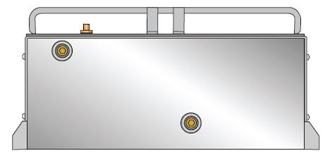
FRONT VIEW