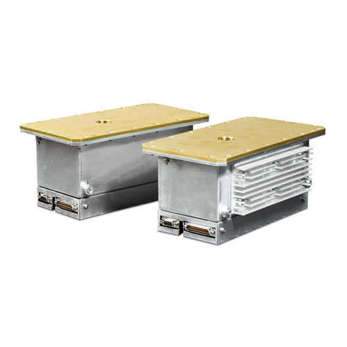
SERIE XRB011
- Fuente de alto voltaje con alimentación de filamento, tubo de rayos X, puerto de haz y electrónica de control integrados
- Compacta y ligera
- Se puede montar en cualquier orientación física
- Interfaz de control analógica o digital
FUENTE DE RAYOS X DE 80 KV, 20 KW-50 KW
La serie XRB011 de fuentes de rayos X Monoblock® de Spellman está diseñada para aplicaciones de OEM en las cuales se energiza su tubo interno de rayos X con 80 kV a 20 W y 80 kV a 50 W. Las funciones tales como el voltaje de entrada de 24 VCD, el tamaño compacto, la interfaz analógica estándar y las interfaces digitales RS-232/Ethernet simplifican la integración de la XRB011 en su sistema de rayos X. El circuito de control de emisión de diseño propio proporciona una regulación excelente de la corriente del tubo de rayos X, además de una sobresaliente estabilidad y desempeño.
Aplicaciones típicas:
- Rayos X médicos: fluoroscopía y radiología para extremidades, radiología de espécimenes.
- Fluoroscopía pulsada (comuníquese con el departamento de ventas de Spellman)
- Rayos X industriales: inspección de componentes y pruebas no destructivas
Especificaciones
(Ref. 128090-001 REV. AF)
X-Ray Characteristics:
Tube Type: Micro focus tube
Focal Spot: 33µm Nominal, 50µm max. (IEC 336)
Beam Filter: Ultem 0.060. (1.5mm)
Oil 0.175. (4.4mm)
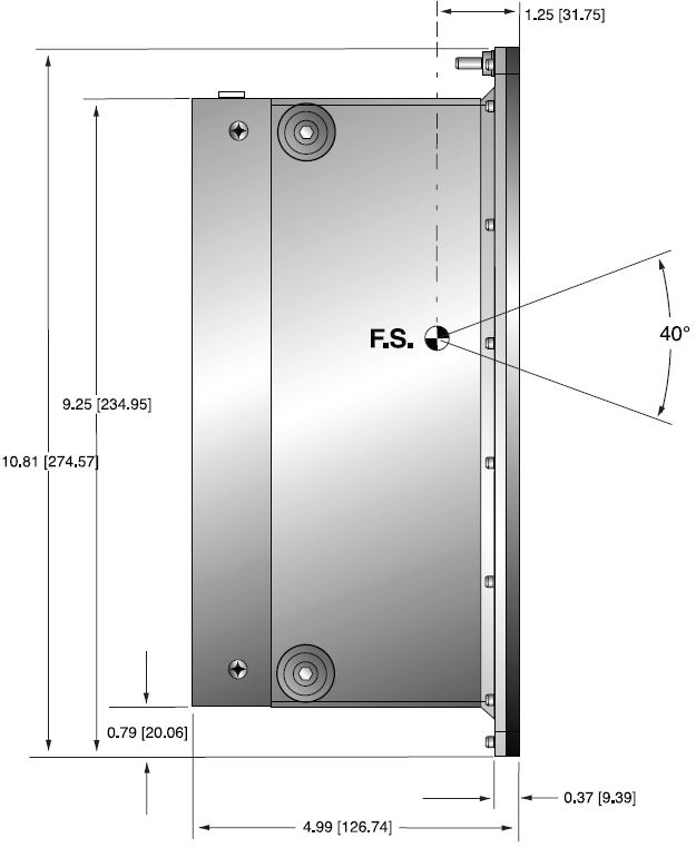
Beam Geometry: Symmetrical 40° cone
Input Voltage:
20W: 24Vdc ±1V @ 2.5A
50W: 24Vdc ±1V @ 4A
X-Ray Tube Voltage:
Nominal X-Ray tube voltage is adjustable between 35kV to 80kV
X-Ray Tube Current:
20W: 0-250µA over specified tube voltage range
50W: 0-700µA over specified tube voltage range
X-Ray Tube Power:
20/50W, maximum continuous
Voltage Regulation:
Line: ±0.5% for a ±1V change of nominal input line voltage
Load: ±0.1% for a load change of 25µA to maximum rated current
Voltage Accuracy:
Voltage measured across the X-Ray tube is within ±1% of the programmed value
Voltage Risetime:
Ramp time shall be =250ms from 10% to 90% of maximum rated output voltage
Voltage Temperature Coefficient:
≤100ppm/°C
Over Temperature Fault:
Indicates that the internal oil temperature has exceeded 65° C. The high voltage output will be disabled. Toggling the X-Ray ON Command OFF and ON will reset the fault.
Over Voltage Fault:
An overvoltage (OV) fault is detected when the output voltage exceeds 82kV. The high voltage output will be disabled. Toggling the X-Ray ON Command OFF and ON will reset the fault.
Voltage Ripple:
1% peak to peak
Current Regulation:
Line: ±0.5% for a ±1V change of nominal input line voltage
Load: ±0.5% for a voltage change of 35kV to 80kV
Current Accuracy:
Current measured through the X-Ray tube is within ±2.5% of the programmed value
Over Current Fault:
An overcurrent (OC) fault is detected when the emission current exceeds 275µA (20W model) and 710µA (50W model). Toggling the X-Ray ON Command OFF and ON will reset the fault.
Arc Intervention:
One arc fault. The high voltage output will be disabled. Toggling the X-Ray ON command OFF and ON will reset the fault.
Filament Configuration:
Internal high frequency AC filament drive with closed loop filament emission control
Analog Interface:
Ground referenced 10kV/V, 25µA/V (20W model) and 70µA/V (50W model) for programming and monitoring analog interface signals. Open collector, active low digital signal interface. Internal jumper is needed to be configured for analog interface.
Digital Interface:
RS-232: standard
Ethernet: optional
Control Software:
A demo GUI is available for engineering evaluations Interlock/Signals: A hardware interlock functions in both analog and digital programming modes.
Operating Temperature:
0°C to +40°C
Storage Temperature:
-20°C to +70°C
Humidity:
10% to 95% relative humidity, non-condensing
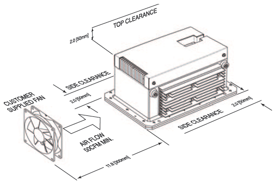
Cooling:
20W and 50W option: Customer provided, external cooling fan, 50cfm, minimum.
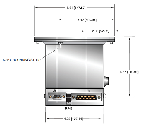
Analog Interface and Input Line Connector:
25 pin D connector, male
Digital Interface Connector:
RS-232: 9 pin D connector, female
Ethernet: RJ45 connector
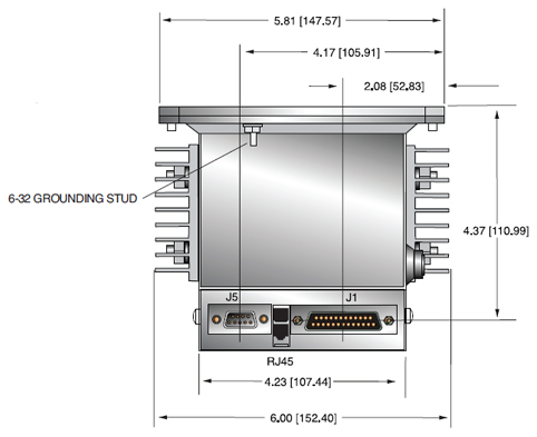
Grounding Point:
6-32 ground stud provided on chassis
Dimensions:
20W: 5.81"W X 5.0"H X 10.81"D (147.57mm X 127mm X 274.57mm)
50W: 6.00"W X 5.0"H X 10.81"D (152.4mm X 127mm X 274.57mm)
Weight:
20W: 18lbs (8.165kg)
50W: 20lbs (9.072kg)
Orientation:
Can be mounted in any orientation.
X-Ray Leakage:
Less than 1mR/hr at 1 meter
Regulatory Approvals:
Compliant to UL/CUL recognized file E242584. CE to EN 61010-1 for non-medical applications.
RS-232 DIGITAL INTERFACE— J5 9 PIN FEMALE D CONNECTOR
| Pin | Signal | Parameters |
|---|---|---|
| 1 | NC | No Connection |
| 2 | TX Out | Transmit Data |
| 3 | RX In | Receive Data |
| 4 | NC | No Connection |
| 5 | SGND | Signal Ground |
| 6 | NC | No Connection |
| 7 | NC | No Connection |
| 8 | NC | No Connection |
| 9 | NC | No Connection |
ETHERNET DIGITAL INTERFACE— RJ45 8 PIN CONNECTOR
| Pin | Signal | Parameters |
|---|---|---|
| 1 | TX + | Transmit Data + |
| 2 | TX -t | Transmit Data - |
| 3 | RX + | Receive Data + |
| 4 | NC | No Connection |
| 5 | NC | No Connection |
| 6 | RX | Receive Data - |
| 7 | NC | No Connection |
| 8 | NC | No Connection |
ANALOG INTERFACE— J1 25 PIN MALE D CONNECTOR
| Pin | Signal | Parameters |
|---|---|---|
| 1 | +24V | +24Vdc±1Vdc @ 4A |
| 2 | +24V | +24Vdc±1Vdc @ 4A |
| 3 | +24V | +24Vdc±1Vdc @ 4A |
| 4 | NC | No Connection |
| 5 | +24V RETURN | +24V RETURN |
| 6 | +24V RETURN | +24V RETURN |
| 7 | +24V RETURN | +24V RETURN |
| 8 | Signal Ground | Signal Ground |
| 9 | Interlock Input | Input, Active low, Interlock is low safe to enable high voltage. Connect to +24V Return |
| 10 | kV Monitor | Output, 0 to 8V = 0 to rated output voltage. Zout=100Ω |
| 11 | μA Monitor | Output, 0 to 10V = 0 to rated output current. Zout=100Ω |
| 12 | X-Ray Ready status | Output, Active Low, Open Collector, 24Vdc @ 10mA max |
| 13 | X-Ray ON status | Output, Active Low, Open Collector, 24Vdc @ 10mA max |
| 14 | Filament Standby status | Output, Active Low, Open Collector, 24Vdc @ 10mA max |
| 15 | Over Voltage Fault | Output, Active Low, Open Collector, 24Vdc @ 10mA max |
| 16 | Over Current Fault | Output, Active Low, Open Collector, 24Vdc @ 10mA max |
| 17 | ARC Fault | Output, Active Low, Open Collector, 24Vdc @ 10mA max |
| 18 | Filament Current Limit Faul | Output, Active Low, Open Collector, 24Vdc @ 10mA max |
| 19 | Signal Ground | Signal Ground |
| 20 | Interlock Output | Output, Active Low, Open Collector, 24Vdc @ 10mA max |
| 21 | μA Program | Input, 0 to 10V = 0 to rated output current. Zin=10kΩ |
| 22 | kV Program | Input, 0 to 8V = 0 to rated output voltage. Zin=10kΩ |
| 23 | X-Ray ON Command | Input, Active low Low (short) = X-Ray ON High (open) = X-Ray OFF Internal pull up resistor to +15V |
| 24 | Signal Ground | Signal Ground |
| 25 | Over Temperature | Active Low, Open Collector, 24Vdc @ 10mA max |
Tablas y Diagramas
DIMENSIONS: in.[mm]
20W Model
ORDERING INFORMATION
Medical Applications:
XRB011-80PN20 80kV, 250uA, 20W, Analog Interface, RS-232
XRB011-80PN20E 80kV, 250uA, 20W, Analog Interface, RS-232, Ethernet
XRB011-80PN20A 80kV, 250uA, 20W, Analog Interface
Non-Medical Applications:
XRB011-80PN20/CE 80kV, 250uA, 20W, Analog Interface, RS-232, CE
XRB011-80PN20E/CE 80kV, 250uA, 20W, Analog Interface, RS-232, Ethernet, CE
XRB011-80PN20A/CE 80kV, 250uA, 20W, Analog Interface, CE
SIDE VIEW
FRONT VIEW
TOP VIEW
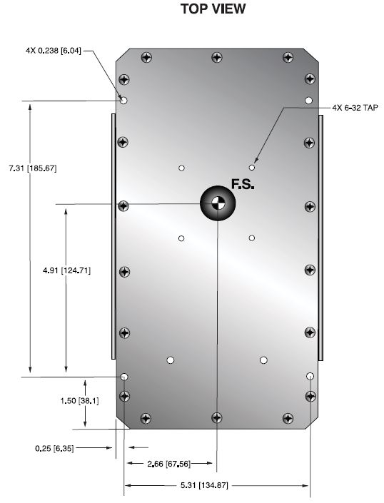
50W Model
ORDERING INFORMATION
Medical Applications:
XRB011-80PN50 80kV, 700uA, 50W, Analog Interface, RS-232
XRB011-80PN50E 80kV, 700uA, 50W, Analog Interface, RS-232, Ethernet
XRB011-80PN50A 80kV, 700uA, 50W, Analog Interface
Non-Medical Applications:
XRB011-80PN50/CE 80kV, 700uA, 50W, Analog Interface, RS232, CE
XRB011-80PN50E/CE 80kV, 700uA, 50W, Analog Interface, RS232, Ethernet, CE
XRB011-80PN50A/CE 80kV, 700uA, 50W, Analog Interface, CE
SIDE VIEW
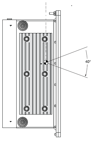
FRONT VIEW
TOP VIEW
Frequently Asked Questions
Why Is Oil Insulation Used?
Do I Need to Ensure My Monoblock® Stays Cool? Why?
How Often Do I Need to Season My Monoblock® X-Ray Source? Why?
Application Notes AN-12 – The Benefit of Using a Current Source to Power X-Ray Tube Filament Circuits