XRB180PN200
- 180kV and 200W
- X-Ray Tube Current: 0.5mA to 1.1mA
- Focal Spot 0.8 x 0.8mm nominal (IEC60336)
- Power factor corrected input to 0.98
- 100Vac to 240Vac, ±10%
*Note: All specifications are subject to change without notice. Please consult the English PDF version of this datasheet for the most up-to-date revision.
XRB180PN200
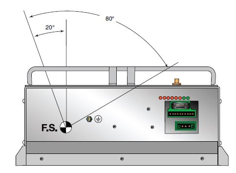
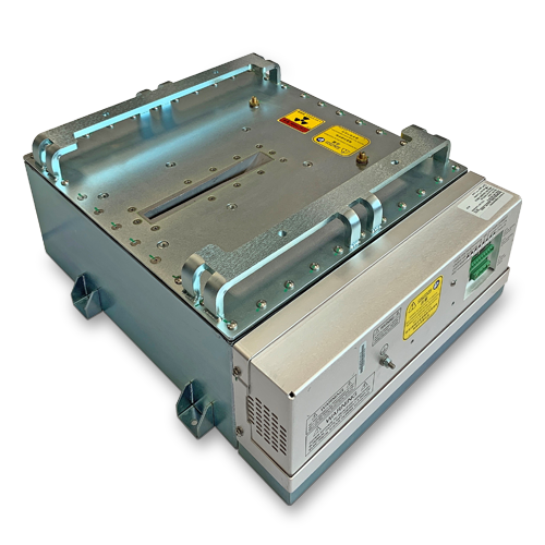
Spellman’s XRB180PN200 is an integrated X-Ray source operating up to 180kV and 200W, providing OEM users a compact plug-and-play Monoblock for critical inspection and screening applications. The unit incorporates a 25° angle stationary anode X-Ray tube offering a fan beam of 80°x 4°. Proprietary emission control circuitry provides excellent regulation of X-Ray tube current, with industry leading dose stability and image quality. This compact model comes with standard analog and RS-232 digital control. Spellman can provide customized versions of this platform for specific OEM system requirements.
TYPICAL APPLICATIONS
Aviation Security Screening: Checked Baggage/EDS, Checkpoint Vehicle Inspection, General NDT, Food Inspection
사양
(Ref. 128085-001 REV. A)
X-Ray Characteristics:
Tube Type: Stationary Anode, tungsten target
Focal Spot: 0.8 x 0.8mm nominal (IEC60336)
Beam Filter: Consists of oil and the curved Ultem 0.079'' +/-0.01''. Inherent filtration in the X-Ray Tube is 1mm Be, 1.5mm +/-10% glass.
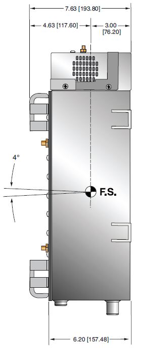
Beam Geometry: Fan of 80° X 4°, ±1%
Anode Angle: 25°
Input Voltage:
Power factor corrected input to 0.98. 100Vac to 240Vac, ±10%, 50/60 Hertz. 5A, maximum
X-Ray Tube Voltage:
Nominal X-Ray tube voltage is adjustable between 90kV to 180kV.
Voltage Accuracy:
The high voltage measured at the X-ray tube will be within ±1% of the selected value.
Voltage Ripple:
Ripple will be ≤0.2% of maximum rated voltage for frequencies ≤1kHz
Voltage Regulation:
< ±0.1% for ±10% of nominal input line change
< ±0.1% for 0.5mA to 1.11mA load change
Voltage Overshoot:
kV overshoot will return within 5% of full voltage in less than 10ms
Risetime:
The voltage and current risetime is controlled by a ramping circuit. Ramp time is less than 0.5 second from 10% to 90% of output voltage and current.
X-Ray Tube Current:
0.5mA to 1.1mA @ 180kV, 200 Watts maximum
Current Accuracy:
<±1% of the selected value.
Current Regulation:
<0.5% at 90-180kV, 0.5mA to 1.1mA
Arc Intervention:
Unit will detect a single arc but HV will not shut down. If multiple arcs occur (4 in 10 seconds) then the unit will shut down.
Filament Configuration:
Internal high frequency AC filament drive operated in current mode with closed loop filament emission control.
Analog Interface:
Ground referenced 0 to 10Vdc for all monitoring signals. Relay contacts and open collector outputs for other signals.
Digital Interface:
Internal high frequency AC filament drive with closed loop filament emission control
Digital Interface:
The RS-232 interface allows for programming of the voltage, current, and X-Ray Enable. Provides monitoring for voltage, current and oil temperature. Tolerance is 3% (with additional 5uA offset at ≤10%mA programming)
Control Software:
A demo GUI is available for engineering evaluation
Operating Temperature:
0°C to +40°C
Storage Temperature:
-40°C to +70°C
Humidity:
10% to 95% relative humidity, non-condensing.
Cooling:
Via natural convection/external cooling fans of 100CFM minimum or maintaining tank/oil temperature below 55°C
Input Line Connector:
3 pin Phoenix Contact, p/n 1829167. Mating connector provided with unit.
Analog Interface Connector:
10 pin Phoenix Contact, p/n 1755503. Mating connector provided with unit.
Digital Interface Connector:
9 pin female D connector. Mating connector provided with unit.
Grounding Point:
M4 grounding stud provided on chassis.
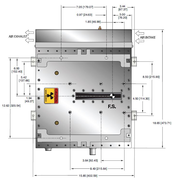
Dimensions:
See outline drawing.
Weight:
132 pounds (60kg).
Orientation:
Can be mounted in any orientation.
X-Ray Leakage:
Not to be greater than .5mR/hr at 5cm from any surface of the Monoblock® when measured at 180kV @ 1.1mA
Regulatory Approvals:
Compliant to EEC EMC Directive. Compliant to EEC Low Voltage Directive.
AC INPUT POWER 3 PIN P/N 1829167
| Pin | Signal | Parameters |
|---|---|---|
| 1 | Line | 100-240Vac,±10%, 50/60 Hertz @ 6 amps |
| 2 | GND | Ground |
| 3 | Neutral | 100-240Vac,±10%, 50/60 Hertz @ 6 amps |
ANALOG INTERFACE— 10 PIN PHOENIX CONTACT P/N 1755503
| Pin | Signal | Parameters |
|---|---|---|
| 1 | X-Ray On | +24Vdc = Enable X-Ray, Low or open = Disable X-Ray |
| 2 | X-Ray On Return | X-Ray on Return |
| 3 | N/C | No Connection |
| 4 | RTN | 0 to 10Vdc = 0 to 200kV, Zout = 10kΩ |
| 5 | kV Monitor | Signal Ground |
| 6 | SGND | 0 to 10Vdc = 0 to 1.5mA, Zout = 10kΩ |
| 7 | Fault | Open Collector, High (Open) = No Fault, 35Vdc @ 10mA, maximum |
| 8 | HV On Lamp N/O | Relay dry contact, normally open, 30Vdc @ <1A, nominal 50mA DC load |
| 9 | HV On Lamp Common | Relay dry contact, common, 30Vdc @ <1A, nominal 50mA DC load |
| 10 | HV On Lamp N/C | Relay dry contact, normally closed, 30Vdc @ <1A, nominal 50mA DC load |
RS-232 DIGITAL INTERFACE— 9 PIN MALE D CONNECTOR
| Pin | Signal | Parameters |
|---|---|---|
| 1 | N/C | No Connection |
| 2 | Receive Data | Conforms to EAI RS-232-C |
| 3 | N/C | N/C |
| 4 | N/C | No Connection |
| 5 | SGND | Signal Ground |
| 6 | N/C | No Connection |
| 7 | N/C | No Connection |
| 8 | N/C | No Connection |
| 9 | N/C | No Connection |
FRONT PANEL LED INDICATORS
| INDICATOR | SIGNAL NAME | CONDITION Illuminated When... | LED COLOR |
|---|---|---|---|
| LED 1 | OT | OverTemperature occurs | Red |
| LED 2 | ARC | Arc fault occurs | Red |
| LED 3 | UV | Low kV occurs | Red |
| LED 4 | OV | High kV occurs | Red |
| LED 5 | UC | Low mA occurs | Red |
| LED 6 | OC | High mA occurs | Red |
| LED 7 | X-RAY ON | X-Rays are enabled | Red |
| LED 8 | PWR ON | Power is ON | Red |
테이블 및 다이어그램
DIMENSIONS: in.[mm
TOP VIEW
SIDE VIEW
BACK VIEW
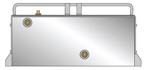
FRONT VIEW