SERIE XRF
- Voltaje de salida de 160 kV
- Para montaje en bastidor
- Filamento flotante
- Alimentación para rejilla interna (modelo de 80 W)
- Corrección de factor de potencia
- Control de emisión de lazo cerrado
- Personalización disponible para OEM

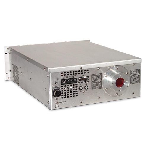
GENERADORES DE RAYOS X INDUSTRIALES DE 80 W-640 W
La plataforma generadora de rayos X XRF de Spellman permite una amplia gama de voltajes de entrada y suministra 80W, 320W o 640W de potencia de salida a hasta 160kVdc. Estos generadores de rayos X livianos de montaje en rack albergan un sistema de alto voltaje miniaturizado en un diseño sólido encapsulado y sin aceite. El generador de rayos X de la serie XRF está diseñado con un circuito de entrada corregido por factor de potencia que reduce las emisiones armónicas y el ruido normalmente asociados con otras fuentes de alimentación conmutadas de alta frecuencia. El generador de rayos X de la serie XRF incorpora un filamento flotante interno y un circuito de control de emisión de lazo cerrado para una regulación precisa de la corriente de emisión. También se proporciona monitoreo y control remoto de voltaje, corriente y corriente de filamento.
APLICACIONES TÍPICAS
Inspección por rayos X, ensayos no destructivos
OPCIONES TÍPICAS
DF Filamento doble
GS Suministro de Grid
SL Opción con Rieles
AT Apaga salida de Alto voltaje en caso de arco.
IOEncendido instantáneo
SS(X) Arranque lento no estándar
Especificaciones
(Ref. 128013-001 REV. T)
SPECIFICATIONS
Input Voltage:
80W: 90-125Vac at 48-62Hz @ 1.9A
180-264Vac at 48-62Hz @ 0.9A
320W: 180-264Vac at 48-62Hz @ 3.5A
640W: 180-264Vac at 48-62Hz @ 7A
Power Factor:
0.9 or better.
High Voltage Supply:
Output Voltage:
0-160kV, negative polarity.
Output Current:
80W: 0.5mA max. 320W: 2.0mA at 160kV 640W: 4.0mA.
Output Voltage Stability:
Within 0.1% of set value after warm-up period at full load.
Output Voltage Ripple:
80W & 320W: <0.1%, or 160V p-p for high freq. and line freq. at full load.
640W: 0.03% rms <1kHz, 0.75% rms above 1kHz.
Beam Current Stability
80W: Within 0.1% of set value after 1/2 hour warm-up at constant output setting of 30-160kV and line voltage of 90-125 & 180-264Vac.
320W & 640W: Same as 80W except line voltage of 180-264Vac.
Filament Supply: Constant current DC filament supply with closed-loop current feedback.
Filament Voltage: 7V rms (high frequency) max.
Filament Current: 5A max., adjustable 0-5.0A by external Filament Limit Programming input.
Floating Grid Power Supply:
Grid Supply: The grid supply controls tube beam current in a closed-loop regulation design.
Grid Voltage: 0 to 1200Vdc.
Grid Voltage Ripple: Less than 1.0V rms at any frequency.
Grid Supply Response: Less than 0.5mA in less than 10ms.
Control and Monitoring:
Analog Control Inputs: Three inputs have internal load resistance greater than 330kohms.
Voltage Programming:
80W, 320W & 640W:
0 to +10Vdc, where 10.0Vdc = 160kV output.
Beam Tube Current Control:
80W: 0 to +10Vdc, where 10.0Vdc = 0.5mA tube current.
320W: 0 to +10Vdc, where 10.0Vdc = 2.0mA tube current.
640W: 0 to +10Vdc, where 10.0Vdc = 4.0mA tube current.
Filament Current Control:
0 to +10Vdc, where 5.0Vdc = 5.0A filament current.
Analog Monitor Outputs: (See tables for details)
Digital Control Inputs: (See tables for details)
Digital Outputs: (See tables for details)
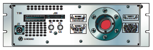
Connections:
Output Connector:
R24 (see owners manual for details)
Input Power Connector:
5-pin male MS-type, Amphenol P/N 97-3102A-18-20P
Control Connector:
25-pin “D” connector, male, chassis-mounted.
Environmental:
0 to +50°C at 10-95% RH, non-condensing.
Forced convection cooling.
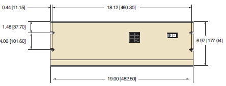
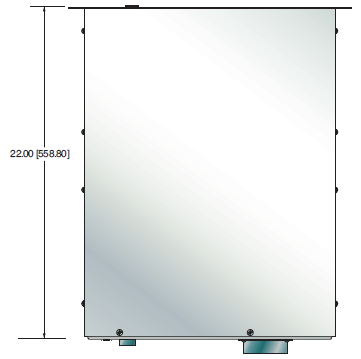
Dimensions:
7”H x 19”W x 22”D (17.8cm x 48.3cm x 55.9cm).
Regulatory Approvals:
Compliant to EEC EMC Directive. Compliant to EEC Low Voltage Directive. RoHS compliant
Options:
DF - Dual Filament AT - Arc Trip
GS - Grid Supply IO - Instant ON
SL - Slides SS(X) - Non Standard Slow Start
Electronic Component (Power Source)
XRF series is intended for installation as a component of a system. It is designed to meet CE standards, with conditions of acceptance often being: customer provided enclosure mounting, EMC filtering, and appropriate protection, and isolation devices. The XRF series is not intended to be operated by end users as a stand-alone device. The XRF series power supply can only be fully assessed when installed within a system, and as a component part within that system.
160kV XRF SELECTION TABLE
| Output Voltage kV | Output Current mA | Output Power W | Model (X NUMBER REQUIRED) |
|---|---|---|---|
| 160 | 0.5 | 80 | X-------- |
| 160 | 2.0 | 320 | X-------- |
| 160 | 4.0 | 640 | X-------- |
J2 AC INPUT CONNECTOR WIRING
| 5 Pin MS Type | 7 Pin UTG Type | Connection |
|---|---|---|
| A | 1 | Auxiliary (Logic) Line |
| B | 2 | Auxiliary (Logic) Neutral |
| C | 3 | Ground |
| D | 4 | Main (Inverter) Line |
| E | 5 | Main (Inverter) Neutral |
JB1 160kV XRF 80W, 320W, 640W 25 PIN
| Pin | Signal | Signal Parameters |
|---|---|---|
| 1 | Filament Limit | 0-5V = 0-5A Filament Limit |
| 2 | High Voltage on Control | +12VDC IN = HV ON |
| 3 | N/C | |
| 4 | N/C | |
| 5 | High Voltage On Status | Low = HV ON |
| 6 | A-Ground | Ground |
| 7 | kV Monitor | 0-10V = 0-160kV |
| 8 | Interlock Control | +12VDC IN = Interlock Closed |
| 9 | N/C | |
| 10 | mA Demand | 0-10V = 0-100% Rated Output |
| 11 | N/C | |
| 12 | N/C | |
| 13 | D-Ground | Ground |
| 14 | Fil. Monitor | 0-5V = 0-5A |
| 15 | N/C | |
| 16 | N/C | |
| 17 | N/C | |
| 18 | N/C | |
| 19 | mA Monitor | 0-10V = 0-100% Rated Output |
| 20 | N/C | |
| 21 | +12VDC Out | |
| 22 | kV Demand | 0-10V = 0-160kV |
| 23 | Grid Inhibit/Fil. Select | Low = Grid Inhibit |
| 24 | N/C | |
| 25 | Chassis Gnd (I/O Shield) | Chassis Gnd. |
160kV XRF 80W, 320W, 640W TERMINAL BLOCK 10 PIN
| Pin | Signal | Signal Parameters |
|---|---|---|
| 1 | Interlock | Jumper to TB1-2 to close interlock |
| 2 | Interlock Return | |
| 3 | kV Monitor | 0-10V=0-160kV |
| 4 | mA Monitor | 0-10V = 0-100% Rated Output |
| 5 | Filament Monitor | 0-5V=0-5A |
| 6 | N/C | |
| 7 | HV ON Indicator | +15V = HV ON |
| 8 | Voltage Mode Indicator | Low = Voltage Mode. |
| 9 | Current Mode Indicator | Low = Current Mode. |
| 10 | GND | Ground |
Tablas y Diagramas
DIMENSIONS: in.[mm]
FRONT VIEW
TOP VIEW
BACK VIEW
Frequently Asked Questions
Application Notes AN-12 – The Benefit of Using a Current Source to Power X-Ray Tube Filament Circuits
Application Notes AN-01 – Fundamentals of X-Ray Generator – X-Ray Tube Optimization

