Specifying High Voltage Power Supplies
by Derek Chambers and Cliff Scapellati
Introduction
In specifying a regulated high voltage power supply for a particular application, it is important to bear in mind that recent advances in power supply technology have made the latest designs smaller, lighter, and more efficient than was possible just a few years ago. New designs generally operate at high frequencies in the range of 20kHz to 100kHz, and industry-wide, have virtually replaced all units operating at line frequency, even at high power levels.
All high voltage power supplies must be operated by personnel familiar with the dangers of high voltage. High voltage sources can be lethal! A general guideline for Safety Practices is found in IEEE Standard 510-1983 "Recommended Practices for Safety in High Voltage and High Power Testing."
The two primary factors which have led to these developments are:
- The availability of key power components which have low losses while operating at high frequency;
- The development of advanced resonant power conversion techniques;
Key Power Components include:
- Faster switching devices (e.g. transistors, power MOSFETS, IGBTs, SCRs);
- Low loss ferrite and powdered iron core materials for choke and transformer cores;
- Capacitors with low dissipation factors;
- Ultra fast rectifiers which have a low forward voltage drop.
- Advanced Conversion Techniques include:
- Zero current switching series and parallel resonant inverters (discontinuous mode);
- Zero voltage switching LCC resonant inverters (continuous mode);
- Soft switching and phase controlled resonant inverters;
- Quasi-resonant flyback and push-pull inverters.
Compared with line frequency operation, high frequencies offer the following advantages in regulated high voltage power supplies:
- Smaller size and weight;
- Faster response time;
- Lower stored energy;
- Higher efficiency;

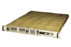
High-voltage supplies such as this multiple-output model use more efficient and higher-performance components and power conversion techniques to reduce weight and improve performance.
Technology
The heart of any high frequency power supply is the oscillator (or inverter) used to drive the output transformer. The specific designs used in the high voltage power supply industry are too numerous to cover in this article since each manufacturer has developed their own proprietary power switching circuits. However, there is one factor, unique to high voltage power supplies that must be considered in the choice of the oscillator or inverter topology. Specifically, the capacitance which exists across the secondary
winding of the step-up transformer must be isolated from being reflected directly across the power switching semiconductors. This isolation can be achieved in a number of ways, including:
- Using a flyback circuit;
- Using an inductor or a series resonant circuit between the switching devices and the transformer;
- Including sufficient leakage inductance between the primary and secondary windings of the transformer;
- Operating as a self resonant oscillator.
The choice of oscillator topology is also influenced by the power level of the supply. For instance, a low power unit for a photomultiplier application could use a flyback or self resonant oscillator, while higher power models (e.g. over a kilowatt) would be more likely to use a driven inverter feeding the output transformer through an inductor or a series resonant circuit. The transformer may also be designed to form part of the resonant inverter power circuit.
Properly designed resonant converter designs offer the following desirable characteristics:
- Zero current switching, which improves efficiency and minimize the switching losses in the high power switching devices;
- Sinusoidal current waveforms in the power inverter circuit, which greatly reduce RFl interference normally associated with pulse width modulation techniques;
- Simple paralleling of the supplies to obtain higher output power;
- Inherent current limiting and short circuit protection of series resonant inverters.
Specification Considerations
Probably the most common mistake engineers make in defining a high voltage power supply is to over specify the requirements for output power, ripple, temperature stability, and size. Such over specification can lead to unnecessarily high cost, and can also lower reliability due to increased complexity and greater power density. If a particular parameter in the catalog specification is inadequate for the application, the factory should be consulted.
Understanding Specification Parameters
The specifications provided by the power supply manufacturer generally include information on the input and output voltages, the output regulation, ripple, and output stability. Often, more detailed information would be useful to the user. In the following sections, power supply parameters are discussed in greater detail than is normally possible on a standard data sheet, and includes definitions and descriptions of requirements encountered by users of high voltage power supplies.
The specification parameters are covered in the following order:
- Input Voltage
- Output Voltage
- Output Current
- Ripple
- Stability
- Stored Energy
- Pulsed Operation
- Line Regulation
- Load Regulation
- Dynamic Regulation
- Efficiency

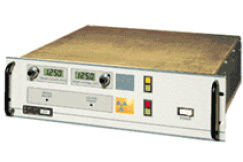
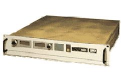
Higher-power high-voltage supplies, like Spellman's series SL which are rated up to 1,200W, operate from ac line power.
I. INPUT VOLTAGE
The input power source specified for a particular model is determined by a number of factors including the output power capability of the supply and the form of power available in the application. In general, low power high voltage supplies having outputs between 1W and 60W typically use a dc input voltage of 24Vdc or 28Vdc, while higher power units operate from the ac power line.
DC Input In many OEM applications, the high voltage supply is just one part of an electronic system in which dc power sources are already available (e.g. 24Vdc, 390Vdc). These existing dc supplies can also be used as the input power source for a high voltage supply. This arrangement is convenient and economical for modular high voltage supplies operating at low power levels.
AC Input Most high power modules over 100W, and rack mounted models are designed for operation from an ac line source. These power supplies are designed to accept the characteristics of the power line normally available at the location of the user, and these can vary significantly in different parts of the world.
In the United States and Canada, the standard single phase voltage is 115/230Vac at 60Hz, while in Continental Europe and in many other parts of the world, the standard voltage is 220Vac at 50Hz. In the UK, the standard is 240Vac at 50 Hz , while in Japan the voltage is normally 100V at 50 or 60Hz. Most power supplies include transformer taps to cover this range, while some new designs cover the range 90Vac to 130Vac and 180Vac to 260Vac without taps. All countries in the European Economic Community will eventually standardize at 230V at 50Hz.
Power Factor correction and universal input at power levels below 3kW can be specified for most off-the-shelf high voltage power supplies. Higher power units require custom engineering.
II. OUTPUT VOLTAGE
High voltage power supplies are generally designed for continuous operation at the maximum output voltage specified in the data sheet. Laboratory bench models and high power rack units are normally adjustable over the complete voltage range from zero to the maximum specified output voltage. In these models, output voltage is indicated on either digital or analog meters, as specified. Modular supplies, on the other hand, may have either a preset output voltage, or a narrow adjustment range, and include monitor terminals instead of meters for measuring the voltage. It is not generally cost effective to specify a power supply with an output voltage greater than 20% over the maximum voltage actually needed in a particular application.
III. OUTPUT CURRENT
Power supplies are normally designed for continuous operation at the full current specified in the data sheet. Current limiting is normally built into the design to prevent overload current from increasing beyond about 110% of the rated maximum value of output current. Overload trip out can usually be specified to disable the power supply when the normal output current is exceeded Current regulation is available on most high power racks and modules. This allows the output current to be controlled by a front panel potentiometer or from a remote source, and provides automatic crossover to voltage regulation when the load current is lower than the programmed value.
IV. RIPPLE
Ripple may be defined as those portions of the output voltage that are harmonically related to both the input line voltage and the internally generated oscillator frequency. In high frequency switching designs it is the combined result of two frequencies, namely, the line frequency- related components and the switching frequency related components. Total ripple is specified either as the rms, or the peak-to-peak value of the combined line frequency and oscillator frequency components, and is normally expressed as a percentage of the maximum output voltage.
to peak in photomultiplier, nuclear instrumentation and TWT applications) to several percent when the output can be integrated over time, such as in precipitators and E-beam welding.
The high frequency ripple may generally be reduced by adding capacitance across the output. On the other hand, when there is a fast response time requirement, the value of output capacitance may have to be reduced. In critical cases, the trade off between slew rate and ripple should be worked out between the customer and the manufacturer of the power supply.
V. Line frequency ripple:
When operating from an ac input source, line frequency ripple can represent a significant part of the total peak to peak ripple. Typically, the power supply is designed to have equal amounts of high frequency and line frequency ripple when operating at full output power. It should be noted that, in most designs, the magnitude of the line frequency ripple is attenuated and controlled by feedback in the regulation circuits, which normally have bandwidths to include the line ripple frequency.
VI. Switching frequency ripple:
In regulated supplies operating from a dc input, line frequency ripple does not exist, and the ripple frequency is simply related to the switching or oscillator frequency of the supply. To reduce switching frequency output ripple, additional filtering components, or sometimes electronic ripple canceling circuits, may be used. When filtering components, such as shunt capacitors or series resistors or inductors, are added to reduce the ripple, they introduce a delay in the control loop circuits which adversely affects the response time of the supply to changes in input or output conditions. The values of the components which control the phase of the signal in the feedback loop are then changed at the factory to maintain stable operation.
If an application requires particularly small values of either high frequency or line frequency ripple, it is usually possible to provide a lower ripple at one of these frequencies at the expense of increasing the ripple at the other. In these special cases, the requirements should be discussed with the factory before an order is placed.
VII. STABILITY
The following factors affect the output stability of a regulated high voltage power supply:
VIII. Drift in the reference voltage;
IX. Offset voltage changes in the control amplifie
X. Drift in the voltage ratio of the feedback divid
XI. Drift in the value of the current sense resist
All these variations are a function of temperature. Stability in a properly chosen reference device is generally less than 5ppm, and offset errors can be virtually eliminated by careful choice of the control amplifier. This leaves the voltage divider and the current sense resistor as the critical items affecting stability in the output voltage and current.
Since these components are sensitive to temperature variations, they are selected to operate at a fraction of their power capability, and are located away from hot components. However, as the power supply warms up and the ambient temperature around the components increases, there are small changes in the ratio of the voltage divider and the value of the current sense resistor which could affect stability.
The values for stability are usually given after a specified warm-up period (typically 1/2 hour). Good stability is achievable by using a divider with a low value of temperature coefficient, although this becomes more costly.
XII. STORED ENERGY
The stored energy at the output of a high voltage power supply can be dangerous to operating personnel, particularly at the higher voltages since its value is a function of the square of the voltage and the value of the capacitance across the output. Certain types of loads, such as X-ray tubes, are also easily damaged by excessive stored energy in the high voltage power supply when an arc occurs. With power supplies operating at high frequency rather than at line frequency, much smaller values of smoothing capacitance can be used, and the dangers of electrocution are thereby reduced. However, it should be noted that low ripple power supplies which include additional filtering capacitance across the output have correspondingly higher amounts of stored energy. Compared with a power supply operating at line frequency, a switching supply operating at 60kHz could have a fraction of the stored energy of an equivalent line frequency supply, since the value of the output capacitance could be reduced by 1000.
XIII. PULSED OPERATION
While some power supplies are designed for dc operation, others can be used in pulsed power applications. In most cases, an energy storage capacitor located inside or external to the supply provides the peak pulse current, and the power supply replaces the charge between pulses. The supply operates in the current mode during the pulse and recharging parts of the cycle, and returns to the voltage mode before the next load current pulse. Pulsed loads generally fall into one of three categories:
XIV. Very narrow pulses (1usec to 10usec), with a duty ratio of < 0.01 to <1%;
XV. Longer pulses (100usec to 1msec), with a duty ratio between 0.05 and 0
XVI. Very long pulses (50msec to 5sec), with a duty ratio between 0.1 and 0
XVII. The first category includes pulsed radar applications in which narrow pulses, having durations in the microsecond range, are generated at typical repetition rates between 500Hz and 5kHz.

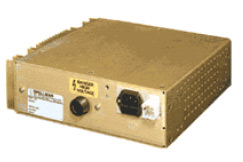
Compact high power module delivers to 350 watts CW or 600 watts pulse for projection television and CRT testing. 1kV to 70kV with voltage and current programming and monitoring.
The second category covers a broader range of applications such as pulsed electromagnet supplies or cable testing where most of the pulse load current is still provided by a capacitor connected across the output. Some modifications to the output and control circuits are usually needed for reliable operation in these applications, and the details of the load characteristics should be discussed with the factory to ensure reliable operation in the customer's system.
The third category requires a power supply specifically designed to provide more current than its average rated value for relatively long periods. Typical applications are medical X-ray systems, lasers and high voltage CRT displays. It is essential that the actual load conditions are completely specified by the user before placing an order.
XVIII. LINE REGULATION
Line regulation is expressed as a percentage change in output voltage for a specified change in line voltage, usually over a ?10% line voltage swing. Measurement is made at maximum output voltage and full load current unless otherwise stated. Line regulation of most high voltage power supplies is better than 0.005%.
XIX. LOAD REGULATION
Load Regulation is specified at full output voltage and nominal line voltage and is expressed as a percentage change in output voltage for a particular load current change, usually no load to full load. Typical load regulation of most high voltage supplies is better than 0.01%.


