Nueva Generación de Equipos de Alimentación de Alto Voltaje
by Cliff Scapellati
ABSTRACT
High voltage power supplies are a key component in electrostatic applications. A variety of industrial and scientific applications of high voltage power supplies are presented for the scientist, engineer, specifier and user of electrostatics. Industrial processes, for example, require significant monitoring of operational conditions in order to maximize product output, improve quality, and reduce cost. New advances in power supply technology provide higher levels of monitoring and process control. Scientific experiments can also be influenced by power supply effects. Contributing effects such as output accuracy, stability, ripple and regulation are discussed.
I. INTRODUCTION
The use of high voltage in scientific and industrial applications is commonplace. In particular, electrostatics can be utilized for a variety of effects. Broadly stated, electrostatics is the study of effects produced by electrical charges or fields. The applications of electrostatics can be used to generate motion of a material without physical contact, to separate materials down to the elemental level, to combine materials to form a homogeneous mixture and other practical and scientific uses. By definition, the ability of electrostatic effects to do work requires a difference in electrical potential between two or more materials. In most cases, the energy required to force a potential difference is derived from a high voltage source. This high voltage source can be a high voltage power supply. Today's high voltage power supplies are solid state, high frequency designs, which provide performance and control unattainable only a few years ago. Significant improvements in reliability, stability, control, size reductions, cost and safety have been achieved. By being made aware of these improvements, the user of high voltage power supplies for electrostatic applications can benefit. Additionally, unique requirements of high voltage power supplies should be understood as they can affect the equipment, experiments, process or product they are used in.
II. OPERATIONAL PRINCIPLES OF HIGH VOLTAGE POWER SUPPLIES
A simplified schematic diagram of a high voltage power supply is shown in Fig. 1.
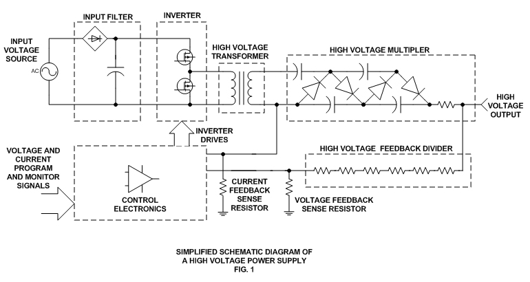
The input voltage source may have a wide range of voltage characteristics. AC sources of 50Hz to 400Hz at less than 24Vac to 480Vac are common. DC sources ranging from 5Vdc to 300Vdc can also be found. It is critical for the user to understand the input voltage requirement as this will impact overall system use and design. Regulatory agencies such as Underwriters Laboratory, Canadian Standards Association, IEC and others are highly involved with any circuits connected to the power grid. In addition to powering the main inverter circuits of the power supply, the input voltage source is also used to power auxiliary control circuits and other ancillary power requirements. The input filter stage provides conditioning of the input voltage source. This conditioning is usually in the form of rectification and filtering in ac sources, and additional filtering in dc sources. Overload protection, EMI, EMC and monitoring circuits can also be found. The output of the input filter is typically a dc voltage source.
This dc voltage provides the energy source for the inverter. The inverter stage converts the dc source to a high frequency ac signal. Many different inverter topologies exist for power supplies. The high voltage power supply has unique factors which may dictate the best inverter approach. The inverter generates a high frequency ac signal which is stepped up by the HV transformer. The reason for the high frequency generation is to provide high performance operation with reduced size of magnetics and ripple reduction storage capacitors. A problem is created when a transformer with a high step up ratio is coupled to a high frequency inverter. The high step up ratio reflects a parasitic capacitance across the primary of the high voltage transformer. This is reflected as a (Nsec:Npri)² function. This large parasitic capacitor which appears across the primary of the transformer must be isolated from the inverter switching devices. If not, abnormally high pulse currents will be present in the inverter.
Another parameter which is common to high voltage power supplies is a wide range of load operations. Due to the presence of high voltage, insulation breakdown is commonplace. The inverter robustness and control loop characteristics must account for virtually any combination of open circuit, short circuit and operating load conditions. These concerns as well as reliability and cost, must be addressed in the High Voltage Power Supply Inverter topology.
The high frequency output of the inverter is applied to the primary of the high voltage step-up transformer. Proper high voltage transformer design requires extensive theoretical and practical engineering. Understanding of magnetics design must be applied along with material and process controls. Much of the specific expertise involves managing the high number of secondary turns, and the high secondary voltages. Due to these factors, core geometry, insulation methods and winding techniques are quite different than conventional transformer designs. Some areas of concern are: volts/turn ratings of the secondary wire, layer to layer insulating ratings, insulating material dissipation factor, winding geometry as it is concerned with parasitic secondary capacitance and leakage flux, impregnation of insulating varnish to winding layers, corona level and virtually all other conventional concerns such as thermal margins, and overall cost.
The high voltage multiplier circuits are responsible for rectification and multiplication of the high voltage transformer secondary voltage. These circuits use high voltage diodes and capacitors in a "charge pump" voltage doubler connection. As with the high voltage transformer, high voltage multiplier design requires specific expertise. In addition to rectification and multiplication, high voltage circuits are used in the filtering of the output voltage, and in the monitoring of voltage and current for control feedback. Output impedance may intentionally be added to protect against discharge currents from the power supply storage capacitors.
These high voltage components are typically insulated from ground level to prevent arc over. The insulation materials vary widely, but typical materials are: air, SF6, insulating oil, solid encapsulants (RTV, epoxy, etc.). The insulating material selection and process control may be the most important aspect of a reliable high voltage design.
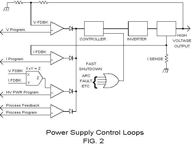
Control circuits keep all of the power stages working together. Circuit complexity can range from one analog I.C. to a large number of I.C.’s and even a microprocessor controlling and monitoring all aspects of the high voltage power. However, the basic requirement which every control circuit must meet is to precisely regulate the output voltage and current as load, input power, and command requirements dictate. This is best accomplished by a feedback control loop. Fig. 2 shows how feedback signals can be used to regulate the output of the power supply. Conventional regulation of voltage and current can be achieved by monitoring the output voltage and current respectively. This is compared to a desired (reference) output signal. The difference (error) between the feedback and reference will cause a change in the inverter control device. This will then result in a change of power delivered to the output circuits.
In addition to the voltage and current regulation, other parameters can be precisely regulated. Controlling output power is easily accomplished by an (X) (Y) = Z function, (V I = W), and comparing it to the desired output power reference. Indeed, any variable found within Ohm's law can be regulated, (resistance, voltage, current and power). In addition, end process parameters can be regulated if they are affected by the high voltage power supply (i.e. coatings, flow rates, etc.).
III. HIGH VOLTAGE REGULATION
The importance of a regulated source of high voltage and/or constant current is critical to most applications involving electrostatics. Variations in output voltage or current can have direct effects on the end results and, therefore, must be understood as a source of error. In high voltage power supplies, the voltage references that are used to program the desired output can be eliminated as a source of significant error by the use of highly stable voltage reference I.C.s. Typical specifications of better than 5ppm/°C are routine. Similarly, analog I.C.s (op amps, A/D D/A's, etc.) can be eliminated as a significant source of error by careful selection of the devices.
There remains one component, unique to high voltage power supplies, which will be the major source of stability errors: the high voltage feedback divider. As seen in Fig. 1, the high voltage feedback divider consists of a resistive divider network. This network will divide the output voltage to a level low enough to be processed by the control circuits. The problem of stability in this network results from the large resistance of the feedback resistors. Values of >100 Meg Ohms are common. This is to reduce power dissipation in the circuit and reduce the effects of temperature change due to self heating. The large resistance and the high voltage rating requires unique technology specific to high voltage resistors. The unique high voltage resistor must be "paired" with a low value resistor to insure ratio tracking under changes of temperature, voltage, humidity and time.
In addition, the high value of resistance in the feedback network means a susceptibility to very low current interference. It can be seen that currents as low as 1 X 10⁻⁹ amps will result in >100ppm errors. Therefore, corona current effects must seriously be considered in the design of the resistor and the resistor feedback network. Also, since much of the resistor technology is based on a ceramic core or substrate, piezoelectric effects must also be considered. It can be demonstrated that vibrating a high voltage power supply during operation will impose a signal, related to the vibration frequency, on the output of the power supply.
IV. AUXILIARY FUNCTIONS INVOLVES WITH THE HIGH VOLTAGE POWER SUPPLY
In many applications of high voltage, additional control functions may be required for the instrument. The power supply designer must be as familiar with the electrostatics application as the end user. By understanding the application, the power supply designer can incorporate important functions to benefit the end process.
A typical feature that can be implemented into a high voltage power supply is an "ARC Sense" control. Fig. 3 shows a schematic diagram of an arc sense circuit. Typically, a current sensing device such as a current transformer or resistor is inserted in the "low voltage side" of the high voltage output circuits. Typically, the arc currents are equal to: I = (E/R) where I = Arc current in amperes.
E = Voltage present at high voltage capacitor.
R = Output limiting resistor in ohms.
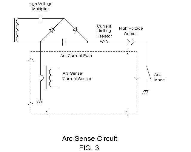
The arc current is usually much greater than the normal dc current rating of the power supply. This is due to keeping the limiting resistance to a minimum, and thereby the power dissipation to a minimum. Once the arc event is sensed, a number of functions can be implemented. "Arc Quench" is a term which defines the characteristic of an arc to terminate when the applied voltage is removed. Fig. 4 shows a block diagram of an arc quench feature.
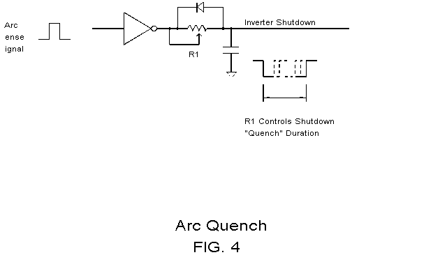
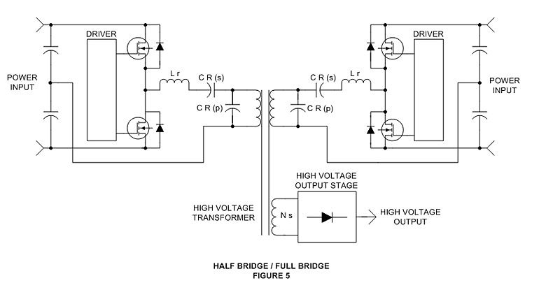
If shutdown is not desired on the first arc event, a digital counter can be added as shown in Fig. 5. Shutdown or quench will occur after a predetermined number of arcs have been sensed. A reset time must be used so low frequency arc events are not accumulated in the counter. Example: A specification may define an arc shutdown if eight arcs are sensed within a one minute interval.
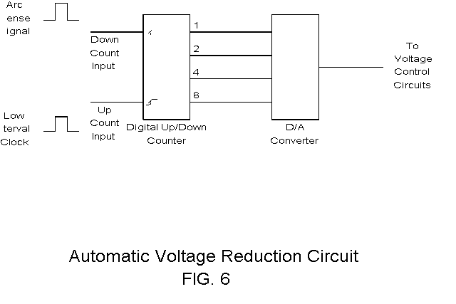
A useful application of the arc sense circuit is to maximize the applied voltage, just below the arcing level. This can be accomplished by sensing that an arc has occurred and lowering the voltage a small fraction until arcing ceases. Voltage can be increased automatically at a slow rate. (Fig. 6).
Another feature which can be found in the high voltage power supply is a highly accurate current monitor circuit. For generic applications this monitor feature may only be accurate to milliamperes, or microamperes. However, in some electrostatic applications accuracy down to femtoamperes may be required. This accuracy can be provided by the high voltage monitoring circuits. However, the user of the power supply usually must specify this requirement before ordering.
V. GENERATING CONSTANT CURRENT SOURCES
In many electrostatic applications, a constant current created by corona effects is desirable. This can be accomplished in a number of unique ways. A constant current source can be broadly defined as having a source impedance much larger than the load impedance it is supplying. Schematically it can be shown as in Fig. 7:
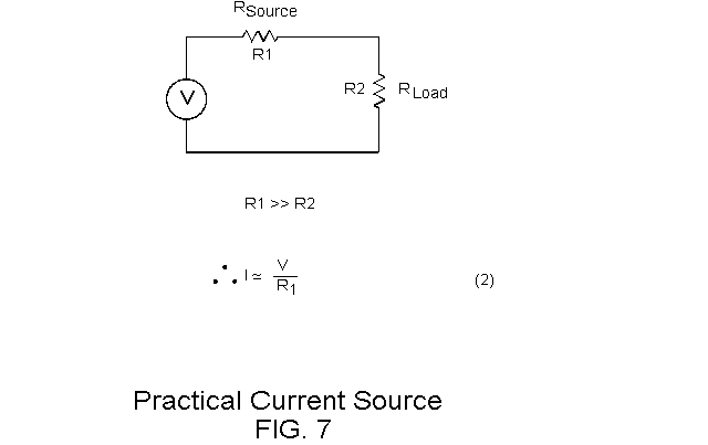
Practically stated, as R2 changes impedance there is negligible effect on the current through R1. Therefore, R1 and R2 have a constant current. In a single power supply application, this can be accomplished two ways. The first is to provide an external resistor as the current regulating device. The second is to electronically regulate the current using the current feedback control as shown in Fig. 2.
In applications where multiple current sources are required, it may not be practical to have multiple power supplies. In this case, multiple resistors can be used to provide an array of current sources. This is typically used where large areas need to be processed with the use of electrostatics. Fig. 8 shows this scheme.
CONCLUSION
This paper presented information useful to electrostatic applications using high voltage power supplies. The high voltage power supply has concerns which differentiate it from conventional power supplies. The designer of high voltage power supplies can be a key resource for the user of electrostatics. Significant control features can be offered by the high voltage power supply. In addition, safety aspects of high voltage use require important attention. High voltage sources can be lethal. The novice user of high voltage should be educated on the dangers involved. A general guideline for safety practices is found in IEEE standard 510-1983 "Recommended Practices for Safety in High Voltages and High Power Testing [4]".
REFERENCES: [1] C. Scapellati, "High Voltage Power Supplies for Analytical Instrumentation", Pittsburgh Conference, March 1995. [2] D. Chambers and C. Scapellati , "How to Specify Today's High Voltage Power Supplies", Electronic Products Magazine, March 1994. [3]D. Chambers and C. Scapellati, "New High Frequency, High Voltage Power Supplies for Microwave Heating Applications", Proceedings of the 29th Microwave Power Symposium, July 1994. [4]IEEE Standard 510-1983, IEEE Recommended Practices for Safety In High Voltage and High Power Testing.
Click here to Download article PDF.


