uXシリーズ
- 50kV、最大50または75ワット
- 65kV、最大65ワット
- 調整可能なアイソレーテッドフィラメント電源
- ローカルとリモートでの放射制御
- RS-232、イーサネット、USBが標準
*注: すべての仕様は予告なく変更される場合があります。最新版についてはこのデータシートの英語PDFをご覧ください。

![]()


50-75W工業用X線発生器
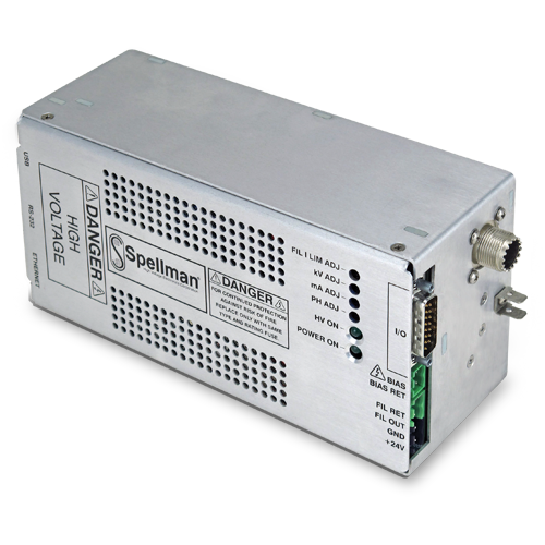
uXシリーズはスペルマンの非常に優れた高電圧パッケージング、表面実装組み立て技術そして独自のポッティング技術を結集させた超コンパクトX線発生モジュールです。主要メーカーのカソード接地型X線管に対応し、0~50kV/65kVの高圧出力、2mAで50W/65W/75Wを供給します。高度にレギュレートされたビーム電流を供給するために閉ループ・フィラメント・ビーム制御回路を利用します。低ノイズDCフィラメント電源は0.3~3.5Aで動作します。厳しいレギュレーション、高い安定度、低リップルのuXは、ーザーにビーム電圧、エミッション電流、フィラメント電流リミットを設定するためのローカル制御とリモート・アナログ制御を備えています。USB, RS-232,Ethernetインターェースが標準装備です。
用途
本モジュールは、Kevex社、Oxford社、RTW社、Varex社、Superior 社、Trufocus社製のカソード接地型X線管に対応しています。
オプション
XCC XRMシリーズと互換性のある高圧ケーブル(50kVのみ)
5VPM 0~5Vのプログラミング、モニター・スケーリング
GB グリッドバイアス・オプション
GF グラウンデッドフィラメント・オプション
5302 uX用Mammoflex高圧ケーブル
2001 XCCオプション付uX用Mammoflex高圧ケーブル
Specifications
(Ref. 128108-001 REV. L)
Input:
+24Vdc ±10%, 5.0A maximum for either 50 Watts or 75 Watts.
+24Vdc ±1V, 5.0A maximum for 65kV/65W units.
Efficiency:
75%, typical
Output:
0 to 50kV at 0 to 2mA, limited to a maximum of 50 watts
or 75 Watts. 0-65kV at 2mA limited to 65 Watts.
Voltage Control:
Local: Internal multi-turn potentiometer to set voltage from 0 to full output voltage.
Remote: 0 to +10Vdc proportional from 0 to full output voltage. Accuracy: ±1%. ZIN: 10Mohm.
Emission Control:
Local: Internal potentiometer to set beam current between 0 and full output current.
Remote: 0 to +10Vdc proportional from 0 to full output current. Accuracy: ±1%. ZIN: 10Mohm. Filament limit and filament preheat control capability is also provided.
DC Filament Supply:
Isolated filament power supply generates emission current feedback signal for accurate low X-Ray tube current performance.
Current: 3.5A, adjustable limit
Voltage: 5.0 volt limit
Environmental:
Operational: 0°C to +50°C
Storage: -40°C to +85°C
Humidity: 0% to 90%, non-condensing
Temperature Coefficient:
0.01% per °C, voltage and current.
Stability:
0.05% per 8 hours after 1/2 hour warm-up.
Voltage and Current Monitors:
0 to +10Vdc proportional from 0 to rated output. Accuracy ±1%.
Redundant Voltage Monitor:
A redundant high voltage feedback divider with proportional 0 to +10Vdc = 0 to 100% output voltage signal can be provided on a custom basis.
Dimensions:
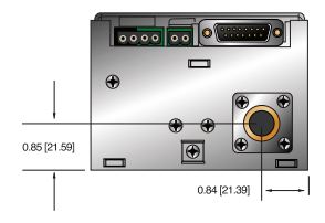
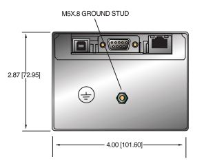
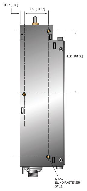
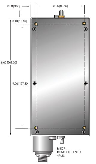
50kV Unit: 4.00”H x 2.87”W x 8.00”D (101.6mm x 72.95mm x 202.20mm).
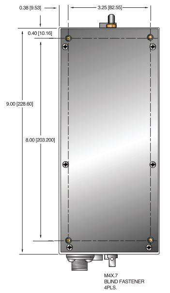
65kV Unit: 4.00”H x 2.87”W x 9.00”D (101.6mm x 72.95mm x 228.60mm).
XCC Option: 4.00”H x 2.87”W x 9.00”D (101.6mm x 72.95mm x 228.60mm).
Weight:
4.5 lbs. (2.1kg) typical
Regulatory Approvals:
Compliant to EEC EMC Directive. Compliant to EEC Low Voltage Directive. RoHS Compliant. UL/CUL recognized, File E227588
Digital Interface
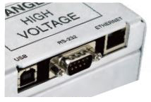
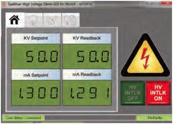
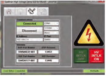
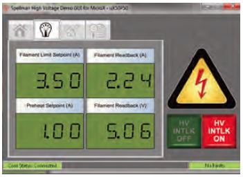
The uX features a standard USB, RS-232 and Ethernet digital interface. Utilizing these standard digital interfaces can dramatically simplify power supply interfacing requirements saving the user both time and money, while enhancing functionality and overall capabiity. Spellman provides a GUI with the uX that allows the customer to both customize operational features of the uX while also providing basic power supply operational features. Details of the uX’s digital interface capability are described in detail in the uX manual.
Closeup showing digital interface connectors
Main Control Screen
Communication Screen
Filament Status Screen
Grid Bias Option (GB):
Spellman’s Grid Bias Option for the uX Series is specifically designed for popular commercially available grid bias X-Ray tubes. The Grid Bias voltage is developed via the use of a separate integrated high frequency switching circuit, providing maximum flexibility and control. The Grid Bias output is a voltage regulated, current compliant topology ideally suited for Wehnelt electrode applications. Arc and short circuit protection of the Grid Bias output prevents any damage due to transient events or installation errors.
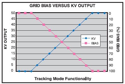
Tracking Mode Operation
Functioning in tracking mode the voltage monitor (0-10Vdc = 0 to 50kV) of the main high voltage output is internally connected to the Grid Bias programming input (0-10Vdc = 0 to -300Vdc of Grid Bias). Connected in this manner the Grid Bias output will track in a linearly proportional fashion the setting of the main kV output.
A multiturn potentiometer limits the maximum magnitude of Grid Bias output applied to the X-Ray tube, providing unparalleled flexibility.
The output of the Grid Bias option is provided via an auxiliary two position Phoenix Contact terminal block, the mating connecter is provided.
Grid Bias Specifications
Output Voltage: 0 to -300Vdc
Output Current: 0.25mA, maximum
Load Regulation: 1% of output voltage, no load to full load
Line Regulation: 1% for a ±10% change in input voltage
Ripple: 1% of maximum rated voltage
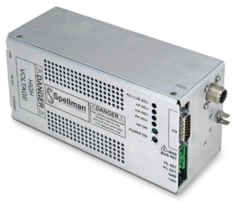
uX with Grid Bias Option
Note: Note: Units ordered with the GB Option will be provided with the XCC Option for proper high voltage cable compatibility.
POWER INPUT/FILAMENT CONNECTOR 4 PIN PHOENIX CONTACT
Spellman drywell type detachable connector.
Standard: A one meter (39.4”) long polyethylene mating high voltage cable is provided.
5302: A one meter (39.4”) long Mammoflex mating high voltage cable is provided, SHV p/n 201946-007.
2001: A one meter (39.4”) long Mammoflex mating high voltage cable is provided, compatible with the XCC Option SHV p/n 201946-002.
POWER INPUT CONNECTOR
| PIN | SIGNAL | PARAMETER |
|---|---|---|
| 1 | +24V Input | +24 volts @ 5A, max. |
| 2 | 24V Return (Gnd.) | Power Ground |
FILAMENT CONNECTOR
| PIN | SIGNAL | PARAMETER |
|---|---|---|
| 1 | Filament Out | 0.3A to 3.5A, 5 volt max.. |
| 2 | Filament Return | Filament Return |
Note: On the standard uX unit, the filament return wire cannot be grounded as this would short circuit the tube return current monitoring to the uX. If grounding of the filament is required, please select the GF (Grounded Filament) option when ordering.
ANALOG INTERFACE CONNECTOR MALE 15 PIN MINI “D”
| PIN | SIGNAL | PARAMETER |
|---|---|---|
| 1 | Monitor Return | Signal Ground |
| 2 | Voltage Monitor | 0-10 volts = 0 to full scale, Zout=1KΩ |
| 3 | Current Monitor | -10 volts = 0 to full scale, Zout=1KΩ |
| 4 | Interlock Output | Connect 12V HVON bulb to pin 15 to enable |
| 5 | +10 Volt Reference | +10 Volts at 1mA, maximum |
| 6 | Filament Monitor | volt = 1 amp, Zout=1KΩ |
| 7 | Voltage Program Input | 0-10 volts = 0 to full scale, Zin=10MΩ |
| 8 | Local Voltage Program* | 0-10 volts, screwdriver adjust |
| 9 | Filament Limit Setpoint* | 1 volt = 1 amp, screwdriver adjust |
| 10 | Current Program Input | 0-10 volts = 0 to full scale, Zin=10MΩ |
| 11 | Local Current Program* | 10 turn pot, screwdriver adjust |
| 12 | Not used (+24V Out for Interlock) | (Optional Interlock configuration) |
| 13 | Not used (Interlock Coil) | (Optional Interlock configuration) |
| 14 | Filament Preheat Setpoint* | 1 volt = 1 amp, screwdriver adjust |
| 15 | Interlock Return | Interlock Ground |
*Denotes 10 turn potentiometer accessable through holes in cover
GRID BIAS CONNECTOR 2 PIN PHOENIX CONTACT
| PIN | SIGNAL | PARAMETER |
|---|---|---|
| 1 | Ground | Chassis Ground |
| 2 | Grid Bias | 0 to -300Vdc |
USB DIGITAL INTERFACE— 4 PIN USB “B” CONNECTOR
| PIN | SIGNAL | PARAMETERS |
|---|---|---|
| 1 | VBUS | +5 Vdc |
| 2 | D- | Data - |
| 3 | D+ | Data + |
| 4 | GND | Ground |
ETHERNET DIGITAL INTERFACE— 8 PIN RJ45 CONNECTOR
| PIN | SIGNAL | SIGNAL PARAMETERS |
|---|---|---|
| 1 | TX+ | Transmit Data + |
| 2 | TX- | Transmit Data - |
| 3 | RX+ | Receive Data + |
| 4 | NC | No Connection |
| 5 | NC | No Connection |
| 6 | RX- | Receive Data - |
| 7 | NC | No Connection |
| 8 | NC | No Connection |
RS-232 DIGITAL INTERFACE— 9 PIN FEMALE D CONNECTOR
| PIN | SIGNAL | SIGNAL PARAMETERS |
|---|---|---|
| 1 | TX+ | Transmit Data + |
| 2 | TX- | Transmit Data - |
| 3 | RX+ | Receive Data + |
| 4 | NC | No Connection |
| 5 | NC | No Connection |
| 6 | RX- | Receive Data - |
| 7 | NC | No Connection |
| 8 | Voltage Monitor 2 | 0-10V = 0 to full scale, Zout = 1KΩ |
| 9 | Power Supply OK | +15V = OK, 0V = Fault, Sink/Source 3mA max |
| How to Order: |
|---|
|
Sample model number: |
| Options are added to the model number as follows: uX50P50/XCC or uX50P75/GB |
Tables & Diagrams
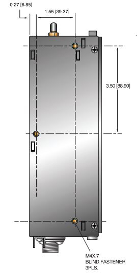
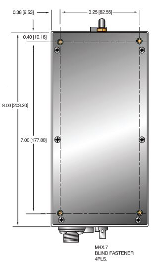
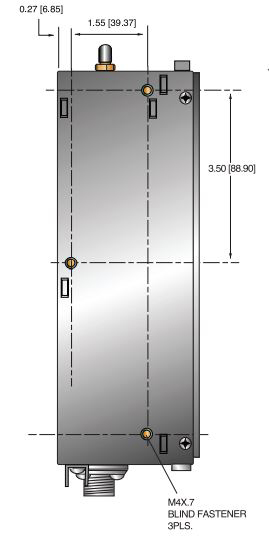
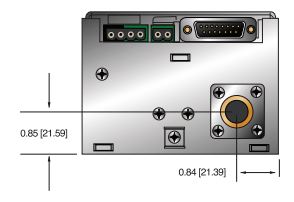
DIMENSIONS: in.[mm]
50KV
BACK VIEW
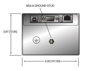
SIDE VIEW
BOTTOM VIEW
FRONT VIEW
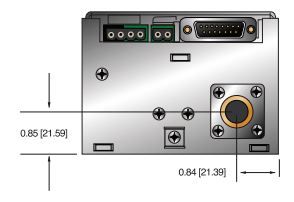
50KV WITH XCC OPTION
BACK VIEW
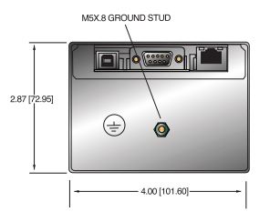
SIDE VIEW
BOTTOM VIEW
FRONT VIEW
65KV
BACK VIEW
SIDE VIEW
BOTTOM VIEW
FRONT VIEW
Frequently Asked Questions
Application Notes AN-12 – The Benefit of Using a Current Source to Power X-Ray Tube Filament Circuits
Application Notes AN-01 – Fundamentals of X-Ray Generator – X-Ray Tube Optimization

