Series PFE - P
- 4kV@1.5A および 6kV@1Aのシステム
- 非常用または補助のPFEとして使用可能
- 電圧、電流のランプレートのアップダウン
- プッシュボタン式電子極性設定
- アラームとトリップ機能
- SMTオプションは、タッチスクリーンコントロール、プログラマブルエレクトロード機能、データ/イベントロギングを提供
*注)仕様は予告なく変更されることがあります。最新の改訂版については、このデータシートの英語版PDFを参照してください。

高圧給電装置(PFE)
スペルマンの船上および陸上給電装置(PFE)は、電気通信の陸上局用海底光ファイバーケーブル中継器やケーブル敷設・修理作業中の給電に使用されています。当社は、海底通信業界における給電装置のリーディングサプライヤーです。
スペルマンのポータブルPFE(PFE-P)は、コンパクトな設置面積で、安定した信頼性と安全性の高い高圧電源を提供します。PFE-Pは、スペルマンの船舶用PFE(PFE-SB)と同じ高度なデジタル管理システムを搭載しており、電圧・電流制御、押しボタンによる極性設定、メインコントロールユニット(MCU)からの連続監視とアラーム報告などが可能です。
オプションのシステム管理ターミナル(SMT)を使用することで、プログラム可能なエレクトロード機能、データおよびイベントのロギング、完全に調整可能なランプレート、トリップおよびアラームを提供するシステムを構成することができます。
システムの電源は、230Vacの単相主電源から供給されます。
(Ref. PFE REV. A)
SPECIFICATIONS
Input Voltage:
230Vac ±10% 50/60Hz (Single Phase)
Input Current:
50A ac maximum at minimum line voltage
Output Voltage:
0 to 6kV, linearly controllable via the MCU
Output Current:
1A maximum at any output voltage up to 6kV
Polarity:
Reversible by selecting positive or negative mode on the MCU when the HV is disabled.
Voltage and Current Ramp Rates:
See MCU and SMT description.
Voltage Ripple:
<0.1% pk-pk of max output +1Vrms
Stability:
Typically <0.25% over any 24 hour period with a temperature range of 0°C to 30°C.
Voltage Regulation:
Load: 0.05% of full voltage +500mV for full load change
Line: +/-0.05% of full voltage +500mV over specified range
Current Regulation:
Load: 0.05% of full current for any voltage change
Line: +/-0.05% of full current over specified input range
Temperature Coefficient:
< 100 ppm/°C
Operating Temperature:
0 to +30°C
Humidity:
0% to 90%, non-condensing
Cooling:
Local cooling and/or ventilation needs to be adequate to balance the system heat dissipation of 1.2kW at 6kV, 1A output.
Safety:
The MCU is equipped with an Emergency Stop Button. Terminals in the rear of the cabinet allow connection of external emergency stop devices.
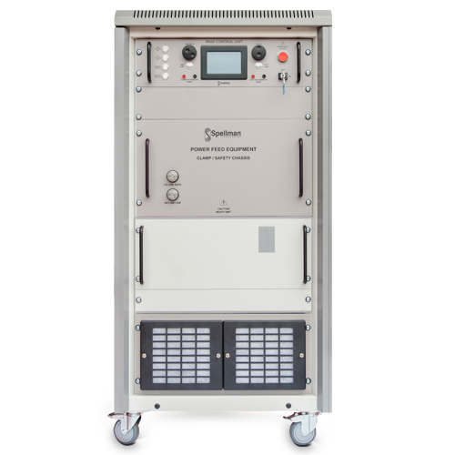
Clamp/Safety Chassis:
Protects the connected line and PFE-P. A HV dump circuit will quickly and safely discharge the system in the event of emergency shutdown Front panel mounted lamps indicate if the PFE-P output is safe or energized.
HV Output:
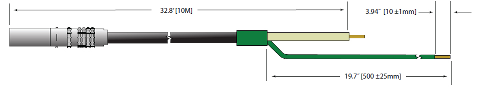
The unit is supplied with 10 meters of RG213/URM67 cable terminated with a 15kV Lemo plug. See HV Output cable detail dwg.
Control:
Manual controls for output voltage and current are provided on the MCU front panel. The PFE-P is capable of operating in either Constant Current or Constant Voltage mode as required by the operator.
Protection:
Over-voltage and Over-current protection levels are settable on the MCU. In the event of a cooling fan failure, the internal temperature limit ensures a safe system shutdown.
Regulatory Approvals:
RoHS compliant. Designed to meet IEC/UL 61010-1 safety requirements for electrical equipment for measurement, control and laboratory use; CAN/CSA-C22.2 No.61010-1.
Specifications
Main Control Unit (MCU):
The system can be controlled manually using the MCU front panel controls.
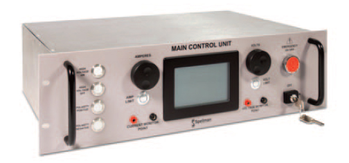
- 4.2” LCD display
- Full output control and monitoring including polarity reversal
- 4mm socket monitor points for voltage and current
- Front panel controls for voltage and current
- Ramp rates available:
Default: 60kV/min 6A/min
Slow: 500V/min 0.2A/min - Over volts/current trips
- HV ON and Alarm outputs provided for customer installation of warning lights and alarms
Interlock System:
Full protection for user and connected equipment. All PFE-P access panels and patch panel connections are interlocked. External connection terminals are provided to allow connection to CTCs, associated equipment or external E-Stop devices.
OPTIONS
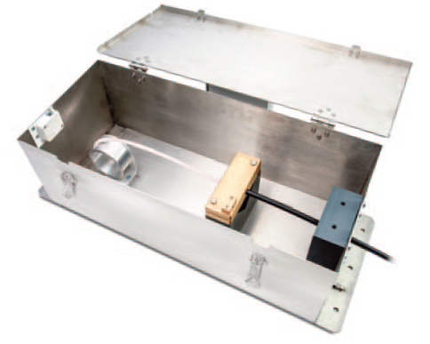
Cable Termination Cubicle (CTC12/377)
Facility to safely accommodate half joints and bare cables for installation and repairs. The CTC provides a safe, interlocked enclosure for connection of the PFE HV to the cable conductors. 2 clamps and strain relief allow the fiber core to be separated and safely routed out of the box to external optical equipment.
W 27.26˝ [692mm]
D 10.44˝ [265mm]
H 8.27˝ [210mm
System Management Terminal (SMT):
The optional SMT is an advanced touchscreen control and monitoring system which can be installed on top of the PFE or remotely up to 80m from the PFE.
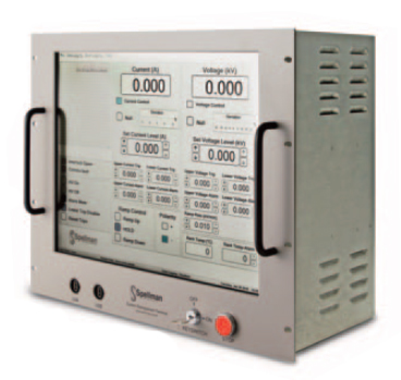
- Full output control and monitoring
- Fully adjustable ramp rates in current or voltage control: 10V-10kV/min and 10mA-10A/min
- User settable over/under voltage and current trips and alarms
- Output voltage and current logging
- Event logging
- Programmable electroding (tone generator 10-40Hz provided)
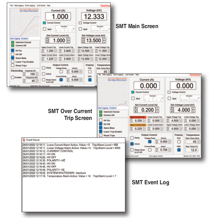
Typical System Management Screens:
DIMENSIONS: in.[mm]
FRONT VIEW
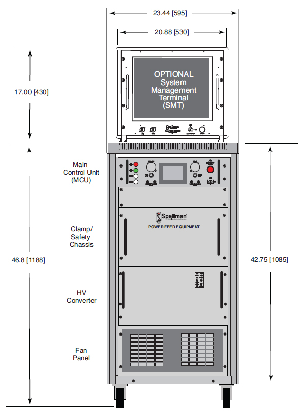
PFE-P Weight Optional SMT 33lbs. [15kg] PFE-P 298lbs. [135kg]
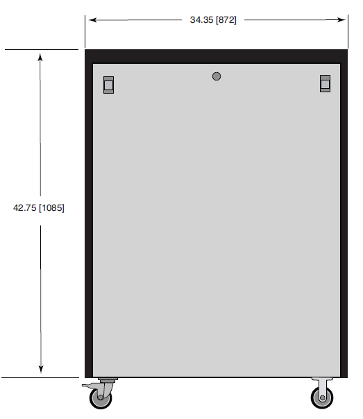
SIDE VIEW
HV Output Cable
The unit is supplied with 10 meters of RG213/URM67 cable. Assembly terminated with a 15kV Lemo plug.