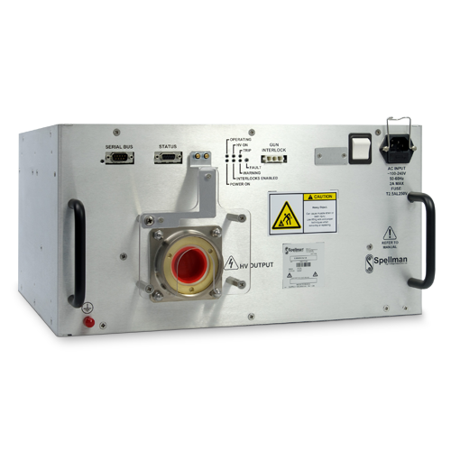
EBM60-FEG
- フィールドエミッションSEM用テトロデサプライを内蔵
- 超低リップル、超安定出力
- 堅牢なアーク・短絡保護回路
- 微小放電を最小化する設計
- RS-232デジタルインタフェース
- テストおよび開発作業用の無料GUI
- CE、UKCA、RoHSマーク取得済み
*注: すべての仕様は予告なく変更される場合があります。最新版についてはこのデータシートの英語PDF版をご覧ください。


フィールドエミッションSEM用テトロデサプライを内蔵
EBM60-FEGシリーズは、電界放出型走査電子顕微鏡(SEM)カラムの駆動用に特別に設計された一体型マルチ高圧電源装置です。スペルマンの広範なアプリケーション知識により、SEMの厳しい要求に応えるためにカスタマイズ可能な様々な技術プラットフォームを開発することができました。
主加速電圧は安定度の高い60kVで、電界放出、冷陰極、ショットキー電子源駆動に必要なフローティングフィラメント、エクストラクタ、サプレッサ出力が内蔵されています。すべての出力は、超低出力リップル、微小放電の最小化、優れたレギュレーション、安定性、温度係数、精度仕様で提供され、これまでにない画質と解像度を実現します。それぞれのフローティング・ソースの絶縁と制御は、スペルマン独自の高電圧絶縁技術によって行われます。
この統合されたEBM60-FEG電源システムは、RS-232インターフェースを介して制御することが可能です。CEおよびUKCAマーク付きです。
代表的なアプリケーション:走査型電子顕微鏡(SEM)
電子ビームコントローラー
(Ref. 128158-001 REV. A)
SPECIFICATIONS
Input Voltage:
100 to 240 Vac ±10% @1A max. 50 to 60 Hz ±5%
Environmental:
Operating Temperature: +10°C to +45°C ambient for normal operation. The unit will operate from 0°C but will require an extended warm up period.
Storage Temperature: -25°C to +60°C
Humidity: 0 to 85% RH, non-condensing
Mechanical:
The unit can be operated in any orientation.
Front Panel Indicators:
-Power On
-Interlocks enabled (both interlocks are closed)
-HV On (any of the HV outputs are enabled)
-Warning (any of the internal warning levels exceeded)
-Operating (unit running correctly)
-Trip
-Fault
-Serial Bus (communication taking place)
Status Outputs:
The unit has three digital outputs to indicate status conditions through TTL signals (high when the corresponding LED is illuminated)
1 - HV on
2 - Fault
3 - Unit Operating
Test GUI:
A product GUI can be provided free of charge for customer testing and development work.
Interlocks:
Two separate interlocks are provided:
Gun interlock: 24V output provided for an external volt free interlock
HV cable interlock: interlock plate mounted over the HV connector
If any interlock is not present: all high voltage supplies including filament are shut down, however communication over the serial interfaces remains operational.
Protection:
-All outputs are protected from arcs in the load (repetition rate up to 0.1 Hz) and continuous short circuit.
-The unit monitors the temperature of the main power semiconductors and shutdown the relevant outputs if a temperature become excessive.
-All low voltage inputs are protected against over voltages of ±30 Volts.
-The power input is protected against over voltage and reversed connection.
Weight:
86 lbs. (39kg)
Regulatory Approvals:
Compliant to EEC Low Voltage Directive. UK Conformity Assessed. RoHS Compliant.
Specifications
OUTPUT SPECIFICATIONS
| Output | Accelerator |
Filament | Supressor | Extractor |
|---|---|---|---|---|
| Output Voltage | -200V to -60kV referenced to ground | nominal 1V max 1.5V referenced to Accelerator | -10V to -1kV referenced to Beam Energy | 200V to 5kV referenced to Beam Energy |
| Output current - max | 300μA | 3A | 100μA | 500μA |
| Current Trip | 350μA ±10% Output disabled and program set to zero | >3.15A for 10s. All outputs disabled and programs set to zero | >120mA ±10% All outputs disabled and programs set to zero |
600μA ±10% All outputs disabled and programs set to zero |
| Accuracy | ±5V | ±5mA (between 2A to 3A) | ±14V | ±2% |
| Linearity | < ± 5V between 500V and 60kV | ±10mA | ±14V | ±2V |
| Load Regulation | <±10ppm for 30μA to 400μA | <5mA for 10% in load resistance | <± 100ppm for 10μA to 90μA | <± 100ppm for 10μA to 500μA |
| Line Regulation or a ± 10% line change | <±10ppm | <1mA | <±10ppm | <±10ppm |
| Ripple p-p at max. output | <120mVp-p at 1Hz to 1MHz | <40mAp-p 20Hz to 10kHz across 0.5Ω @ 2.5A | <10mVp-p at 1Hz to 1MHz | <50mV p-p at 1Hz to 1MHz |
| Temperature Coefficient | <20 ppm/°C at 60kV after 1h warm up | <20 ppm/°C | <50 ppm/°C | <25 ppm/°C |
| Stability (1h warm up) | <15ppm or 40mV (whichever is greater) /10min | <30ppm/10min and 5mA/3 months @ 2.5A | <100ppm/10min | <20ppm/10min |
| Voltage Monitor Resolution | 1.14V | 62.5μV | 19mV | 97mV |
| Voltage Monitor Accuracy | ±1% or ±50V | ±5% or ±25mV |
±0.5% or ±0.5V | ±0.5% or ±3V |
| Current Monitor Resolution | 5.7nA | 62.5μA | 2.3nA | 11nA |
| Current Monitor Accuracy | ±1μA | ±1% or ±5mA | ±2μA | ±0.5% or ±2μA |
| Additional info | Programmable Wobble feature. Sinusoidal, 0V to 500V p-p, 0.2Hz to 2Hz |
Open Circuit detection: Vout > 3.1 ± 0.1V All outputs disabled and programs set to zero. Optimized for a nominal load resistance of 0.5Ω |
GUN INTERLOCK CONNECTOR 3 PIN MATE-N-LOK
(TE CONN. P/N: 1-350943-0)
| PIN | SIGNAL | I/O | PARAMETER |
|---|---|---|---|
| 1 | Interlock | I | 24V Return |
| 2 | N/C | - | |
| 3 | Interlock + | I | 24V Drive |
STATUS OUTPUT CONNECTOR 9 PIN FEMALE D
| PIN | SIGNAL | I/O | PARAMETER |
|---|---|---|---|
| 1 | HV ON | O | High voltage status, logic high* when any of the HV outputs is enabled |
| 2 | HV ON GND | - | High voltage status return |
| 3 | Fault | O | Fault status, logic high* when any internal fault is detected |
| 4 | Fault GND | - | Fault status return |
| 5 | UO | O | Unit Operating status, logic high* when the unit is running correctly |
| 6 | UO GND | - | Unit Operating status return |
| 7 | N/C | - | No connection |
| 8 | N/C | - | No connection |
| 9 | N/C | - | No connection |
*TTL Signal: High > 2.7V, Low <0.8V
RS-232 COMMUNICATION CONNECTOR 9 PIN MALE D
| PIN | SIGNAL | I/O | PARAMETER |
|---|---|---|---|
| 1 | N/C | - | No connection |
| 2 | RS232 TXD | I | RS-232 receive data |
| 3 | RS232 TXD | O | RS-232 transmit data |
| 4 | N/C | - | No connection |
| 5 | GND | - | Ground |
| 6 | N/C | - | No connection |
| 7 | N/C | - | No connection |
| 8 | N/C | - | No connection |
| 9 | N/C | - | No connection |
INPUT POWER CONNECTOR
I.E.C. 320 Receptacle with integral fuse
HIGH VOLTAGE OUTPUT CONNECTOR
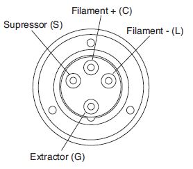
The unit uses a Claymount CA4 75kV 4 pin receptacle. Mating cable assemblies in different lengths are available. See HOW TO ORDER table.


HOW TO ORDER
| Description | Part Number |
|---|---|
| EBM60-FEG | EBM60N18/FEG |
| HV Output Cable - 3 meters | HVC75/4SO/1365 |
| HV Output Cable - 4 meters | HVC75/4SO/1366 |
Tables & Diagrams
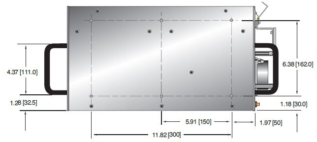
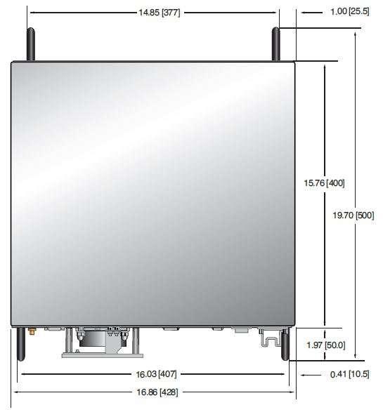
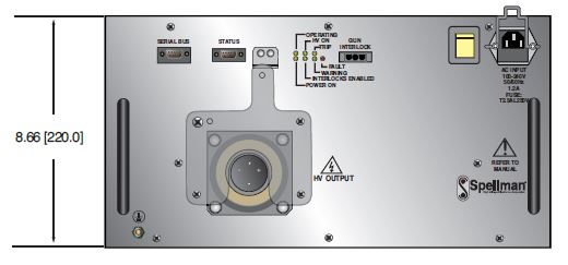
DIMENSIONS: in.[mm]
SIDE VIEW
TOP VIEW
REAR VIEW

