SERIE XRB150PN600
- Fuente de alto voltaje con alimentación de filamento, tubo de rayos X, puerto de haz y electrónica de control integrados
- Compacta y ligera
- Factor de potencia corregido
- Se puede montar en cualquier orientación física
- Interfaz de monitoreo analógica e interfaz digital estándar RS-232
FUENTE DE RAYOS X DE 150 KV, 160 W
El generador de rayos X XRB150PN600 Monoblock® de Spellman está diseñado para aplicaciones OEM que alimentan su tubo de rayos X interno de hasta 150 kV a 600 W. Características como la corrección del factor de potencia, el tamaño pequeño y una interfaz analógica estándar y RS-232 digital simplifican la integración de esta unidad en su sistema de rayos X. Los modelos estándar están disponibles con geometría de haz en forma de cono. Los circuitos patentados de control de emisiones proporcionan una excelente regulación de la corriente del tubo de rayos X, junto con un rendimiento de estabilidad excepcional.
Aplicaciones típicas:
- Barrido de rayos X: densitometría ósea
- Inspección de alimentos
- Seguridad
Especificaciones
(Ref. 128079-001 REV. G)
X-Ray Characteristics:
Tube Type: Glass tube, Tungsten target, Be filter
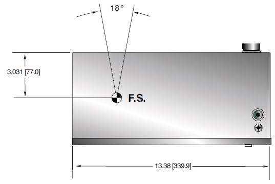
Focal Spot: 0.5mm x 0.5mm (IEC 336)
Beam Filter: 0.06. Ultem
Beam Geometry: Cone up to 18° ±1°
Input Voltage:
Vac, 50/60Hz, 6.5A maximum 200-240 +/-10%
X-Ray Tube Voltage:
Nominal X-Ray tube voltage is adjustable between 70kV to 150kV
X-Ray Tube Current:
1.0mA to 4.0mA over specified tube voltage range
X-Ray Tube Power:
160W continuous, 600W peak Duty Cycle: 30 seconds on, 300 seconds off @ 600W peak
Voltage Regulation:
Line: ±0.1% for a ±10% input line change of 180 to 264Vac
Load: ±0.1% for a 1.0mA to 4.0mA load change. 600W maximum
Voltage Accuracy:
Voltage measured across the X-Ray tube is within ±2% of the programmed value
Voltage Risetime:
±1% in less than 300ms
Voltage Overshoot:
±10% during 300ms risetime
Voltage Ripple:
1% rms of rated voltage @ 10Hz to 1MHz
Current Regulation:
Line: ±0.1% from 180-264Vac
Load: ±0.5% @ 70-150kV, 1.0mA to 4.0mA
Current Accuracy:
Current measured through the X-Ray tube is within ±2% of the programmed value
Current Risetime:
±1% in less than 300ms
Arc Intervention:
4 arcs in 10 seconds with a 200ms quench = Shutdown
Filament Configuration:
Internal high frequency AC filament drive with closed loop filament emission control
Analog Interface:
0 to 5Vdc ground referenced signals
Digital Interface:
RS-232 interface.
Control Software:
A demo GUI for engineering evaluations will be provided for the RS-232 digital interface upon request.
Interlock/Signals:
A hardware interlock function is provided
Operating Temperature:
0°C to +40°C
Storage Temperature:
-40°C to +70°C
Humidity:
10% to 95% relative humidity, non-condensing
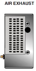
Cooling:
External fan required. 250cfm minimum to maintain an oil temperature of 55C° or less.
Input Line Connector:
3 pin Phoenix Contact P/N 1829167
Analog Interface Connector:
10 pin Phoenix Contact P/N 1755503
Digital Interface Connector:
9 pin D connector, female
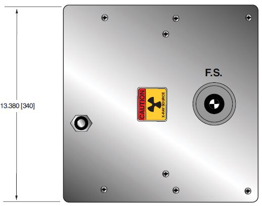
Grounding Point:
8-32 ground stud provided on chassis
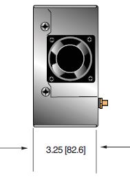
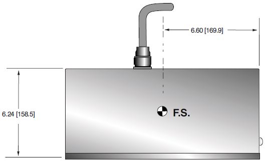
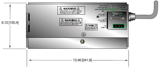
Dimensions:
13.46" X 13.38" X 6.24"
(341.89mm X 339.85mm X 158.50mm)
Weight:
66lbs (30kg)
Orientation:
Can be mounted in any orientation.
X-Ray Leakage:
Less than 100mR/hr at 1m distance, measured at 140kV, 3mA.
AC INPUT POWER JB1 3 PIN PHOENIX CONTACT
| Pin | Signal | Parameters |
|---|---|---|
| 1 | Line | 180-264Vac |
| 2 | GND | Chassis Ground |
| 3 | Neutral | Neutral |
RS-232 DIGITAL INTERFACE— JB16 9 PIN FEMALE D CONNECTOR
| Pin | Signal | Parameters |
|---|---|---|
| 1 | Spare | N/C |
| 2 | Transmit | RS-232 |
| 3 | Receive | RS-232 |
| 4 | Spare | N/C |
| 5 | Signal Ground | Ground |
| 6 | Spare | N/C |
| 7 | Spare | N/C |
| 8 | Spare | N/C |
| 9 | Spare | N/C |
ANALOG INTERFACE— JB15 10 PIN PHOENIX CONTACT
| Pin | Signal | Parameters |
|---|---|---|
| 1 | X-Ray Signal | +12Vdc =Enable X-Ray, 0Vdc/open = Disable X-Ray, Zin=1kΩ |
| 2 | X-Ray Signal Return | Signal Return |
| 3 | N/C | N/C |
| 4 | kV Monitor | 0 to 5Vdc = 0 to 175kV, Zout= 10kΩ |
| 5 | Signal Ground | Signal Ground |
| 6 | mA Monitor | 0 to 5Vdc = 0 to 4.5mA, Zout= 10k |
| 7 | Fault Signal | Open collector, High (Open) = No Fault, 35Vdc @10mA maximum |
| 8 | HV ON Lamp Relay n/o | Relay Normally Open, 50Vdc @ 1A maximum |
| 9 | HV ON Lamp Relay common | Relay Common, 50Vdc @ 1A maximum |
| 10 | HV ON Lamp Relay n/c | Relay Normally Closed, 50Vdc @ 1A maximu |
LED INDICATORS
| Indicator | Signal Name | Condition Illuminated When... |
|---|---|---|
| LED 1 | OT | Over temperature occurs |
| LED 2 | ARC FLT | Arc fault occurs |
| LED 3 | UV | Low kV occurs |
| LED 4 | OV | High kV occurs |
| LED 5 | UC | Low mA occurs |
| LED 6 | OC | High mA occurs |
| LED 7 | X-RAY ON | X-Rays are enabled |
| LED 8 | PWR | Power is ON |
Tablas y Diagramas
DIMENSIONS: in.[mm]
FRONT VIEW TANK
SIDE VIEW TANK
TOP VIEW TANK
FRONT VIEW
CONTROL ASSEMBLY
SIDE VIEW
CONTROL ASSEMBLY
SIDE VIEW
CONTROL ASSEMBLY