")
XRB160PN480/CT Monoblock® Industrial X-Ray Generators
- Integrated HV Supply, Filament Supply, X-Ray Tube, Beam Port and Control Electronics
- Compact & Lightweight
- Can be Mounted in Any Physical Orientation
- Standard RS-232 Digital Interface
*Note: All specifications are subject to change without notice. Please consult the English PDF version of this datasheet for the most up-to-date revision.
![]()
160kV, 480W X-Ray Source
Spellman’s XRB160PN480/CT Monoblock® X-Ray source is designed for OEM applications powering its internal X-Ray tube up to 160kV at 480W. Features like small package size and RS-232 digital interface simplify integrating this Monoblock® into your X-Ray system. Standard models are available with fan shaped beam geometry. Proprietary emission control circuitry provides excellent regulation of X-Ray tube current, along with outstanding stability performance.
Typical applications:
- X-Ray Scanning: Food Inspection
- Fill Level Confirmation
- Security Applications
Specifications
(Ref. 128083-001 REV. J)
X-Ray Characteristics:
Tube Type: Glass tube, Tungsten target, Be filter
Focal Spot: 0.8mm x 0.8mm (IEC336)
Beam Filter: 1.75mm of glass, 1mm of Al, and 10mm of oil
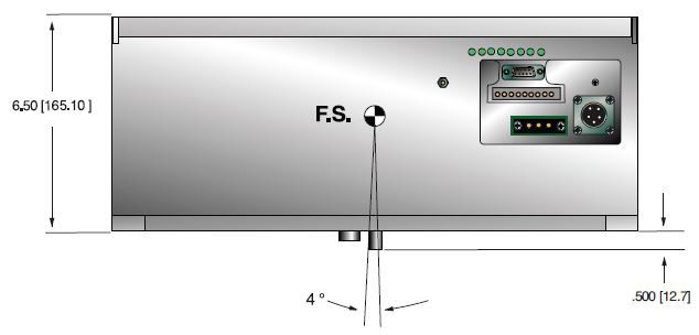
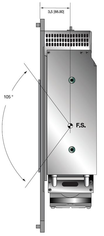
Beam Geometry: Symmetrical fan 105° ±3° x 4° ±1°
Input Voltage:
Monoblock®: 100-240Vac ±10%, 50/60Hz, 6.5A max
Heat Dissipation Unit: 24Vdc, 3A
X-Ray Tube Voltage:
Nominal X-Ray tube voltage is adjustable between 20kV to 160kV
X-Ray Tube Current:
0.3mA to 6mA over specified tube voltage range
X-Ray Tube Power:
320W continuous, 480W peak
Voltage Regulation:
Line: ±0.1% for a ±10% input line change of nominal input line voltage
Load: ±0.1% for a 0.3mA to 6mA load change
Voltage Accuracy:
Voltage measured across the X-Ray tube is within ±1% of the programmed value
Voltage Risetime:
Ramp time shall be <1 second from 1% to 90% of rated output
Voltage Overshoot:
Within 5% of rated voltage
Voltage Ripple:
0.1% p p of rated voltage @ ≤1kHz
Current Regulation:
Line: ±0.5%
Load: ±0.5%
Current Accuracy:
Current measured through the X-Ray tube is within ±1% of the programmed value
Current Risetime:
<1 second from 1% to 90% of rated output
Arc Intervention:
4 arcs in 10 seconds = Shutdown
Filament Configuration:
Internal high frequency AC filament drive with closed loop filament emission control
Digital Interface:
RS-232
Control Software:
A demo GUI for engineering evaluations will be provided for the RS-232 digital interface upon request.
Interlock Signals:
A hardware interlock functions in digital programming modes.
Operating Temperature:
0°C to +40°C
Storage Temperature:
-40°C to +70°C
Humidity:
5% to 90% relative humidity, non-condensing
Cooling:
Heat exchanger w/fan and oil pump, powered from AC
Input Line Connector:
3 pin Phoenix Contact part no. 1829167
Digital Interface Connector:
9 pin D, female
Grounding Point:
8-32 ground stud provided on chassis
Dimensions:
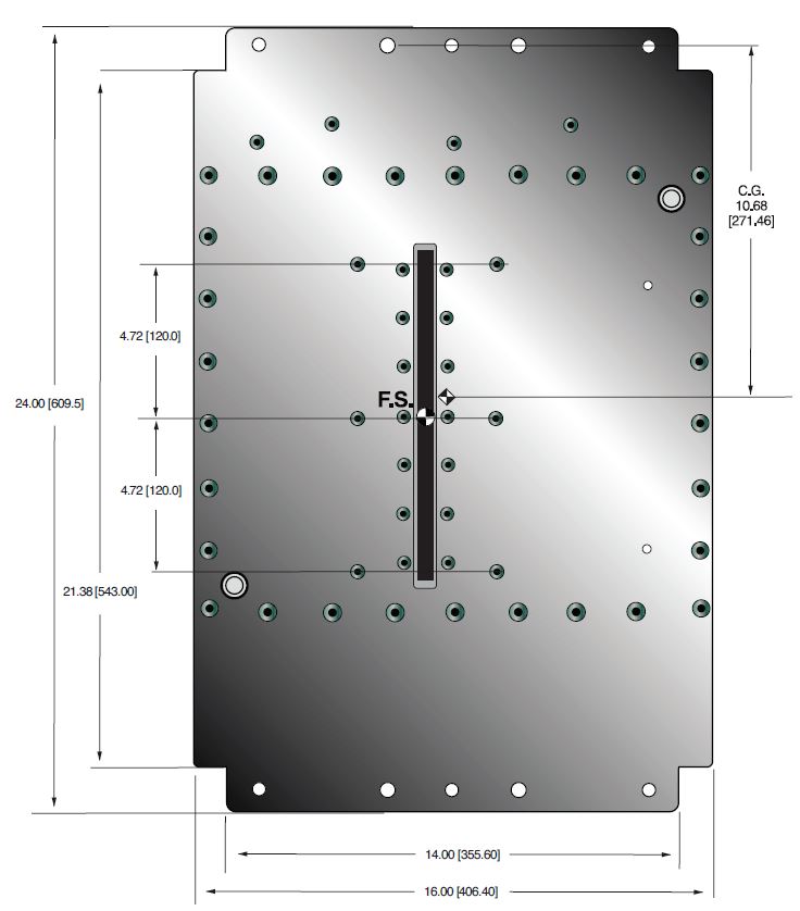
24.00˝ x 16.00˝ x 6.50˝ (609.60mm x 406.40mm x 165.10mm)
Weight:
125lbs (49.5kg) ±10lbs (±4.5kg)
Orientation:
Can be mounted in any orientation.
X-Ray Leakage:
Not to be greater than 0.5mR/hr at 5cm outside the external surface
Special Features:
Stationary or rotating CT application up to 90rpm at a max. radius of 24.75˝ (629mm) Corporate
AC INPUT POWER 3 PIN PHOENIX CONTACT
| Pin | Signal | Parameters |
|---|---|---|
| 1 | Line | Line |
| 2 | GND | GND |
| 3 | Neutral | Neutral |
ANALOG INTERFACE — 10 PIN PHOENIX CONTACT
| Pin | Signal | Parameters |
|---|---|---|
| 1 | X-Ray | +24Vdc = enable X-Ray |
| 2 | X-Ray Return | X-Ray Return |
| 3 | N/C | No Connection |
| 4 | kV Monitor Output | 0 to 9Vdc = 0 to 100% Rated Voltage |
| 5 | SGND | Signal Ground |
| 6 | mA Monitor Output | 0 to 9Vdc = 0 to 100% Rated Current |
| 7 | Fault | Open Collector, Open = No Fault |
| 8 | Relay N/C | HV On, 50V @ 1A maximum |
| 9 | Relay Common | HV On, 50V @ 1A maximum |
| 10 | Relay N/O | HV On, 50V @ 1A maximum |
RS-232 DIGITAL INTERFACE — 9 PIN FEMALE D CONNECTOR
| Pin | Signal | Parameters |
|---|---|---|
| 1 | N/C | No Connection |
| 2 | Transmit Data | Conforms to E/A RS-232-C |
| 3 | Receive Data | Conforms to E/A RS-232-C |
| 4 | N/C | No Connection |
| 5 | SGND | Signal Ground |
| 6 | N/C | No Connection |
| 7 | N/C | No Connection |
| 8 | N/C | No Connection |
| 9 | N/C | No Connection |
Tables & Diagrams
DIMENSIONS: in.[mm]
FRONT VIEW
BACK
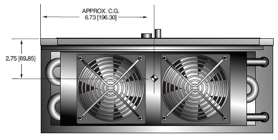
TOP VIEW
SIDE VIEW
Frequently Asked Questions
Why Is Oil Insulation Used?
Do I Need to Ensure My Monoblock® Stays Cool? Why?
How Often Do I Need to Season My Monoblock® X-Ray Source? Why?
Application Notes AN-12 – The Benefit of Using a Current Source to Power X-Ray Tube Filament Circuits

