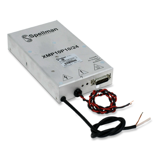
XMPG СЕРИЯ
- Выходное напряжение от 4 кВ до 10 кВ
- Встроенный источник питания нити накала с опорным выходным напряжением относительно земли
- Низкий уровень пульсации
- Локальное и дистанционное программирование
- Возможность изготовления по спецификациям заказчика
* Примечание: Все спецификации могут быть изменены без предварительного уведомления. Пожалуйста, ознакомьтесь с английской версией PDF этой спецификации для получения последней актуальной информации об оборудовании.
4kV - 10kV X-Ray Generator
XMPG представляет собой модульный рентгеновский генератор мощностью 10 кВ при 10 Вт, предназначенный для питания рентгеновской трубки с заземленной нитью накала посредством замкнутого контура управления током эмиссии от 0 до 1 мА. Заземленный источник питания накала рассчитан на 0–5 А при 3 В постоянного тока. Источник питания накала снабжен внутренним регулируемым предварительным подогревом на 0,5–2,5 А и внутренним регулируемым ограничителем нити накала на 0–5 А.
Для программируемых настроек высокого напряжения и тока эмиссии предлагаются предустановленные значения, упрощающую взаимодействие с этим рентгеновским генератором. Также пользователь может использовать сигнал 0–10 В постоянного тока для дистанционного управления этими двумя параметрами. Предусмотрен сигнал контроля высокого напряжения и сигнал контроля тока эмиссии.
Вход разрешающего сигнала ВН обеспечивает управление наличием выходного высокого напряжения, а выход стабильного состояния нити накала дает обратную связь о том, что ток нити накала стабилен и что рентгеновская трубка генерирует рентгеновское излучение.

Технические характеристики
(Ref. 128122-001 REV. A)
SPECIFICATIONS
Input Voltage:
+24 Vdc, ±10%
Input Current:
2 amp maximum
Output Voltage:
10kV, controllable over the range 4kV to 10kV
Voltage Accuracy:
<2%
Polarity:
Positive
Voltage Regulation:
Line: <0.01% for input voltage change of ±10%
Load: <0.01% for zero to full load
Voltage Stability:
< 0.1% per 24 hours at constant operating conditions, after 30 minutes warm up
Ripple:
< 500mV p-p of output voltage at full load
Ramp Rate:
< 20kV/second
Temperature Coefficient:
<250ppm per degree C
Current Regulation:
Line: ≤0.01% for 1V input voltage change under any load conditions
Load: ≤0.01% for full load to short circuit
Emission Current:
0-1mA
Current Accuracy:
<1% (above 10% of maximum output current)
Current Stability:
< 0.02%
Environmental:
Temperature Range:
Operating: 5˚C to 40˚C
Storage: -40˚C to 70˚C
Environmental:
Humidity:
Operating: 20% to 80% RH, non-condensing
Storage: 5% to 95%
Filament Supply:
Voltage: 0V to 3Vdc referenced to ground
Load Current: 5A max, preset adjustable limit
Stability: < 0.25% per 8 hours at constant operating conditions
Ripple: <50mV p-p (at maximum load current).
Temperature Coefficient: <300ppm/˚C
Filament Output:
A captive 500mm long unterminated 16 AWG twisted wire pair is provided.
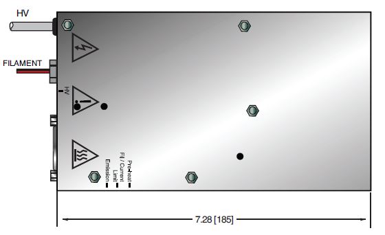
High Voltage Output:
A captive 500mm long unterminated length of URM76 shielded cable
A red High Voltage On LED is provided next to the high voltage output to indicate that high voltage is being produced by the unit
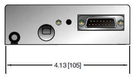
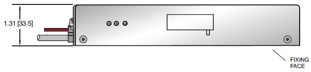
Dimensions:
1.31”H x 4.13”W x 7.28”D (33.5mm x 105mm x 185mm)
Regulatory Approvals:
Compliant to CE Safety marking to meet the requirements of EN61010, Installation cat II, safety class 1, poll. degree 2 and UL61010A-1 and CSA 1010.
As the unit is designed for incorporation within the users system it is not tested against any specific EMC standards. The user will need to take sensible EMC precautions when designing the unit in and verify the overall system EMC performance against any relevant standards. RoHS compliant.
FILAMENT OUTPUT
| COLOR | NAME |
|---|---|
| Red | Filament + |
| Black | Filament - |
CUSTOMER INTERFACE— 15 PIN MALE D CONNECTOR
| Pin | Signal | Parameters |
|---|---|---|
| 1 | +24Vdc |
+24Vdc |
| 2 | Ground | Ground |
| 3 | Preheat (set value) | 0-5Vdc from internal preset |
| 4 | Test (Filament Current Direct Program) | Do not connect |
| 5 | HV Enable | Digital Input |
| 6 | Filament Stable | Digital Output |
| 7 | HV Program Output | 0-10Vdc from Internal Preset |
| 8 | HV Program Input | 0-10Vdc Input |
| 9 | High Voltage Monitor | 0-10Vdc Output |
| 10 | Emission Current Monitor | 0-10Vdc Output |
| 11 | Filament Current Monitor | 0-10Vdc Output |
| 12 | Emission Current Program Input | 0-10Vdc Input |
| 13 | Emission Current Program Output | 0-10Vdc from Internal Preset |
| 14 | Ground | 0-10Vdc from Internal Preset 14 Ground |
| 15 | Preset Max. Filament Current (set value) | 0-10Vdc from Internal Preset |
The filament Preheat level and current limit are set by internal preset potentiometers accessible through the side of the case. If external high voltage enable control is not required link pins 7 and 8. If external emission current control is not required link pins 12 and 13.
Таблицы и диаграммы
DIMENSIONS: in.[mm]
FRONT VIEW
TOP VIEW
BOTTOM VIEW
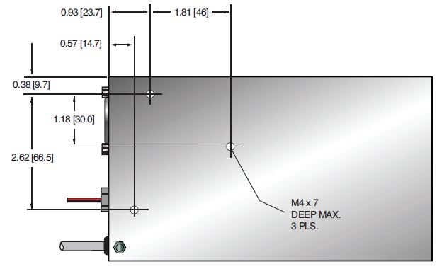
SIDE VIEW
FAQ
УП-12 – ПРЕИМУЩЕСТВО ИСПОЛЬЗОВАНИЯ ИСТОЧНИКА ТОКА ДЛЯ ПИТАНИЯ ЦЕПЕЙ НАКАЛА РЕНТГЕНОВСКИХ ТРУБОК

