FIB
- 加速器・イオン源統合シャーシ
- 高性能グラウンドリファレンスレンズシャーシ
- 超低リップル、超安定出力
- 堅牢なアークおよびショートサーキット保護
- 微小放電イベントを最小化する設計
- 光学的に絶縁されたデジタルインターフェース
- CEマーク取得済み、SEMI S2準拠のデザイン
注)仕様は予告なく変更されることがあります。最新の改訂版については、このデータシートの英語版PDFを参照してください。


FIB
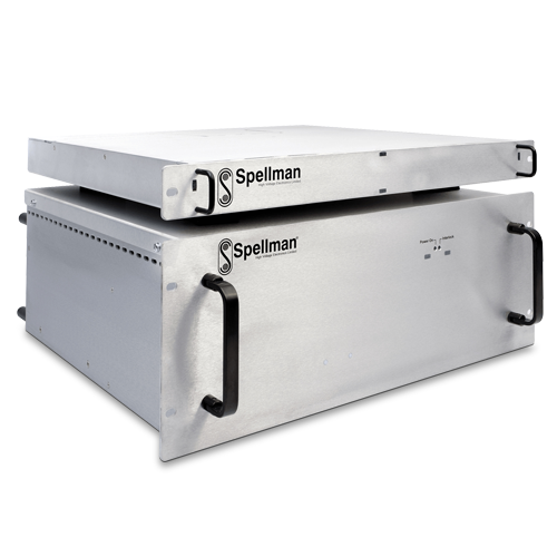
スペルマンのFIBシリーズは、集束イオンビームアプリケーション用に特別に設計された、統合された複数出力の高圧電源です。従来のGaイオンおよびプラズマソースを駆動するために、フローティング出力を備えた、高い安定性の加速電源が組み込まれています。
またイオンビームの集束に必要な、高性能の固定または極性反転を有するレンズ用高圧電源を提供する、追加のレンズシャーシが利用可能です。メインシャーシとレンズシャーシは、どちらも19インチラックに取り付け可能です。 集束イオンビームは、半導体産業、材料科学で使用されることが多いですが、材料のイメージング、エッチング、堆積のために生物学分野で使用されることが増えてきています。
メインシャーシは、最大35kVの加速電圧を提供し、フローティングフィラメント、エクストラクタ、およびサプレッサ出力を備え、すべてFIBアプリケーションの厳しい性能要件に合わせて設計されています。レンズシャーシは、固定または極性反転を有する、最大30kVのレンズ用電圧を提供します。
すべての出力は、超低出力リップル、優れたレギュレーション、安定性、温度係数、ドリフトおよび正確な仕様で提供されます。各フローティングソースの分離と制御は、スペルマン独自の高電圧分離技術によって提供されます。
お客様によるこの統合されたFIB電源システムの制御は、光ファイバーもしくはイーサネットインターフェイスを介して行われます。すべての高圧安全インターロックは、フェイルセーフハードウェアベースの設計です。
代表的なアプリケーション:
- 集束イオンビーム(FIB)
- イオンガンコントローラー
Specifications
(Ref. 128029-001 REV. C)
SPECIFICATIONS
Input Voltage:
+24Vdc, ±5% @ 5.5 amps maximum. Inrush is <6 amps for 1 second.
Environmental:
Operating Temperature:
+10°C to +45°C ambient for normal operation. The unit will operate from 0°C but will require an extended warm up period.
Storage Temperature:
-20°C to +60°C
Humidity:
0 to 80% RH, non-condensing
Altitude:
2000 meters ASL at full power. For altitudes above 2000 meters the maximum ambient operating temperature is linearly derated by 1.1˚C per 300 meter interval.
FIB Input Power Connector:
2 pin Mate-n-Lok (TE 1-350942-0)
FIB Communication:
Fiber Optics dual channel Avago HFBR- 2524z/1524z. RS-232. Ethernet RJ-45 socket which supports 100BaseTX. When Ethernet port is connected, RS-232 will not work. A Spellman Fiber Optic to RS-232 converter can be ordered, as well as a complete Fiber Optic to USB communication kit.
FIB Vacuum Interlock Connector:
Dual channel Avago HFBR- 2524z (receiver) /1524z (transmitter)
FIB to Lens Modules Interconnection:
The modules are supplied with interconnecting cables for the power and communications. The same kit is used to connect the FIBC to the lens module, and, if required, between a lens module and the next.
FIB HV Output Connector:
The main high voltage output is fitted with a custom 4 pole receptacle. A Spellman HV cable assembly, available in different lengths, can be ordered with the unit.
Lenses HV Output Connectors:
The lenses are fitted with Lemo ERA3Y430CTL receptacles. A Spellman 5 meters mating HV cable assembly can be ordered with the units. (See the product manual for additional cables and connectors information)
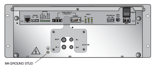
Safety Interlocks:
The vacuum interlock is an optical interlock. When it opens, the power supply is deactivated via relay contacts and will not reactivate until it is enabled through the computer control, even though the interlock may close. The FIB communication remains operational.
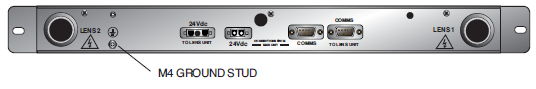
The interlock plate is situated around the FIB HV Output connector, and if removed will also disable all outputs.
The individual modules of the HVPS can be enabled and disabled through computer control, provided the appropriate hardware interlocks are enabled.
Weight:
Main chassis: 67.46 lbs. (30.6 kg)
Lens chassis: 27.56 lbs. (12.5 kg)
Regulatory Approvals:
Compliant to EEC Low Voltage Directive. UK Conformity Assessed. RoHS Compliant.
OUTPUT SPECIFICATIONS
| MODULE | FIBC35 | LGM | |||
|---|---|---|---|---|---|
| OUTPUT | Accelerator | Filament | Suppressor | Extractor | Lens |
| Output Voltage | 0 to 35kV, referenced to ground | 0 to 5V referenced to Accelerator, current controlled | -2kV to +2kV referenced to Accelerator | 0 to -15kV referenced to Accelerator | 30kV max, referenced to ground, positive, negative or bipolar. (see Lens Module options table) |
| Output current max | 30μA | 5A | 30μA | 400μA | 30μA or 50μA (see config. table) |
| Output current limit | 30μA | current controlled | 30μA | programmable 8 bit, 0 to 400μA | 30μA or 50μA ( see config. table) |
| Output Absolute Accuracy | 100V | 5mA | 20V | 100V | 100V |
| Load Regulation | ±0.01% of max for 0 to 30μA change | ±0.1% of max for 0 to 5V change | ±0.01% of max for 0 to 30μA change | ±0.01% of max for 0 to 400μA change | ±0.005% of max for 0 to max rated current change |
| Line Regulation | 100mV for a 5% line change | 5mA for a 5% line change | 100mV for a 5% line change | 100mV for a 5% line change | 100mV for a 5% line change |
| Ripple p-p from 0.1Hz to 1MHz | 200mV at max output | 10mA | 150mV | 100mV at 30μA and below | 200mV for 30kV bipolar outputs.150mV for all other output ratings |
| Temperature Coefficient | 25 ppm/°C | 200 ppm/°C | 25 ppm/°C | 25 ppm/°C | 25 ppm/°C |
| Stability (after 2h warm up) | 1.5V / 10h | 5mA/10min | 0.5V / 10h | 0.5V / 10h | 1V / 10h |
| Programming | 16 bit, 0 to 35kV | 16 bit, 0 to 5A | 16 bit, -2kV to +2kV | 16 bit, 0 to -15kV | 16 bit, min to max Vout |
| Voltage Monitoring |
16 bit, 0 to 35kV ±1% accuracy ±50V offset |
16 bit, 0 to 5V ±4% accuracy ±0.1V offset |
16 bit, -2kV to +2kV ±1% accuracy ±8V offset |
16 bit, 0 to -15kV ±1% accuracy ±15V offset |
18 bit, min to max Vout, ±1% accuracy ±15V offset |
| Current Monitoring |
16 bit, 0 to 30μA ±1% accuracy ±0.3μA offset |
16 bit, 0 to 5A ± 4% accuracy ±50mA offset |
N/A |
16 bit 0 to 10μA: 16 bit 10μA to 400μA: |
18 bit, min to max Iout ±3% accuracy ±1μA offset |
| Response (See note 1) |
<1.0 s | <0.1 s | <0.25 s | <0.25 s | <0.1 s, <4 sec to reach <2V away from steady state for 20kV to 18kV and 18kv to 20kV change |
| Additional info | see note 2 | see notes 3 and 4 | |||
Note 1:
This is the time taken for the output signal of a module to settle (to 0.2% of the step size, or 1 V (20 mA for the filament), whichever is greater) in response to a ±2% or less (of full scale) step in its output, as measured from when the output first starts to change.
Note 2:
Hard trip at 400μA in < 0.25s programmable trip delay (for when current at I limit) 0 to 255s, 8 bit res., (5s min, 20s default)
Note 3:
The above specifications do not apply in the range -500V to +500V
Note 4:
Wobble range: 2V to 2.5kV p-p, sinusoidal. If wobbling occurs near zero, the wobble waveform will be clipped so as to prevent crossing zero.
Wobble Period: 1s to 4s
LENS MODULES
| Available as Standard | Lens 1 Output | Lens 2 Output | ||
|---|---|---|---|---|
| Part number | Voltage | Current | Voltage | Current |
| LGM30P/25PN | 0V to +30kV | 30uA | -25kV to +25kV | 30uA |
| LGM30P/30P | 0V to +30kV | 30uA | 0V to +30kV | 30uA |
| LGM30P/25N | 0V to +30kV | 30uA | 0V to -25kV | 30uA |
| Available on Request | Lens 1 Output | Lens 2 Output | ||
| LGM20PN/30PN | -20kV to 20kV | 30uA | -30kV to +30kV | 30uA |
| LGM30N/25PN | 0V to -30kV | 30uA | -25kV to +25kV | 30uA |
| LGM20N/10N | 0V to -20kV | 50uA | 0 to -10kV | 50uA |
Please consult with factory for availability and custom configuration requests.
Tables & Diagrams
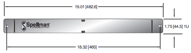
Lens Chassis
DIMENSIONS: in.[mm]
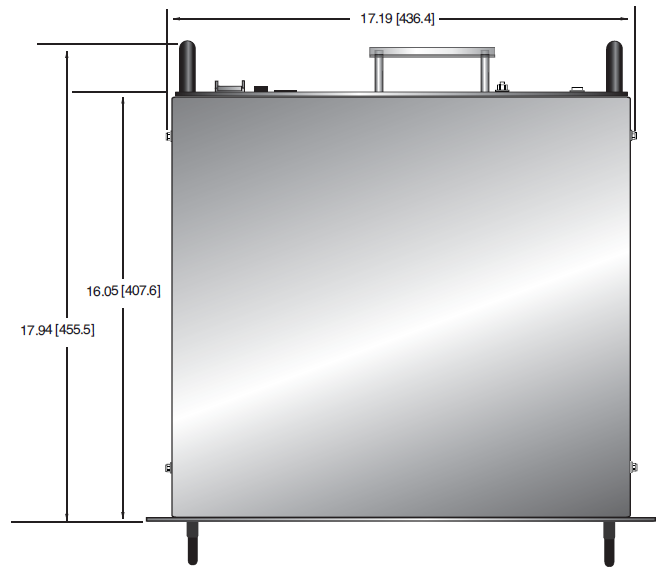
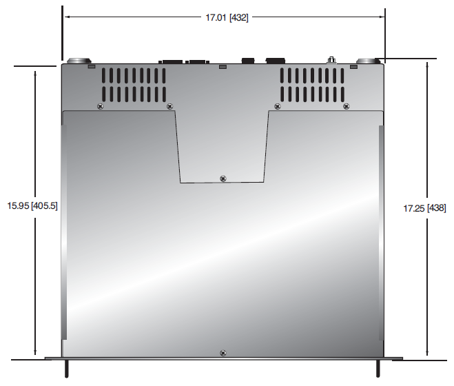
Main Chassis
DIMENSIONS: in.[mm]
TOP VIEW
FRONT VIEW
REAR VIEW
Lens Chassis
DIMENSIONS: in.[mm]
TOP VIEW
FRONT VIEW
REAR VIEW
HOW TO ORDER
| Description | Part number |
|---|---|
| FIB - Main Chassis | FIBC35 |
| LGM - Lens Chassis | See part number in the Lens Modules Table |
| FIBC to Lens Modules Interconnection kit |
FIBK826 |
| FIBC HV Output cable | 2.8 meters: HVC30/4ISO/1209 5 meters: HVC30/4ISO/1297 |
| Lens HV Output cable | 5 meters: HVC30/1S/1253 |
| FIB communication kit | FIBK100 |
| Optical to RS-232 converter | 21777 |


