")
XRB160PN192 Monoblock® Industrial X-Ray Generators
- Integrated HV Supply, Filament Supply, X-Ray Tube, Beam Port and Control Electronics
- Compact & Lightweight
- Universal Input, Power Factor Corrected
- Can be Mounted in Any Physical Orientation
- Analog Monitoring and Standard RS-232 Digital Interface
*Note: All specifications are subject to change without notice. Please consult the English PDF version of this datasheet for the most up-to-date revision.
![]()
160kV, 200W X-Ray Source
Spellman’s XRB160PN192 Monoblock® X-Ray source is designed for OEM applications powering its internal X-Ray tube up to 160kV at 192W. Features like universal input, small package size and a standard analog and RS-232 digital interface simplify integrating this Monoblock® into your X-Ray system. Standard models are available with fan shaped beam geometry. Proprietary emission control circuitry provides excellent regulation of X-Ray tube current, along with outstanding stability performance.
Typical applications:
- X-Ray Scanning: Plating Measurement
- Food Inspection
- Fill Level Confirmation
- Security Applications
Specifications
(Ref. 128082-001 REV. M)
X-Ray Characteristics:
Tube Type: Glass tube, Tungsten target, Be filter
Focal Spot: 0.8mm x 0.8mm.
Beam Filter: 0.016. thick 6061 Al.
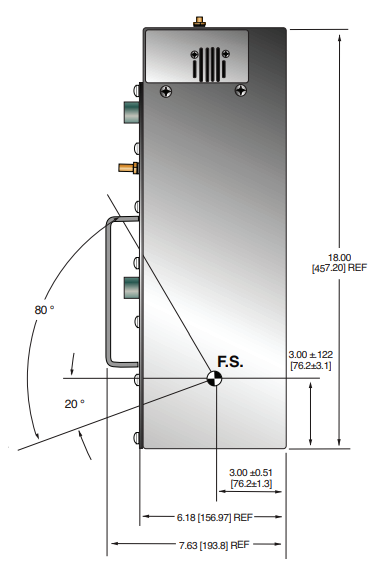
Beam Geometry: Asymmetrical fan 80° x 10° +/-2°
Input Voltage:
100-240Vac, 50/60Hz, 5A maximum +/-10%
X-Ray Tube Voltage:
Nominal X-Ray tube voltage is adjustable between 80kV to 160kV
X-Ray Tube Current:
0.1mA to 1.2mA, 192W maximum over specified tube voltage range
X-Ray Tube Power:
192W, maximum continuous
Voltage Regulation:
Line: ±0.1% for a ±10% input line change of nominal input line voltage Load: ±0.1% for a 0.1mA to 1.2mA load change
Voltage Accuracy:
Voltage measured across the X-Ray tube is within ±2% of the programmed value
Voltage Risetime:
Ramp time shall be <200ms from 10% to 90% of rated output
Voltage Overshoot:
Within 5% of rated voltage in <10ms
Voltage Ripple:
1% p p of rated voltage @ =1kHz
Current Regulation:
Line: ±0.1% for a ±10% input line change of nominal input line voltage
Load: 0.5% @ 80-160kV, 0.1mA to 1.2mA
Current Accuracy:
Current measured through the X-Ray tube is within ±2% of the programmed value
Current Risetime:
<200ms from 10% to 90% of rated output
Arc Intervention:
4 arcs in 10 seconds with a 200ms quench = Shutdown
Filament Configuration:
Internal high frequency AC filament drive with closed loop filament emission control
Analog Interface:
0 to 10Vdc ground referenced signals
Digital Interface:
RS-232 interface.
Control Software:
A demo GUI for engineering evaluations will be provided for the RS-232 digital interface upon request.
Interlock Signals:
A hardware interlock function is provided
Operating Temperature:
0°C to +40°C
Storage Temperature:
-40°C to +70°C
Humidity:
10% to 95% relative humidity, non-condensing
Cooling:
Natural convection augmented by customer provided 250cfm cooling fans for 192W operatio
Input Line Connector:
6 pin Molex 26-60-4060
Analog Interface Connector:
7 pin Molex 26-60-5070
Digital Interface Connector:
9 pin D connector, female
Grounding Point:
32 ground stud provided on chassis
Dimensions:
18" X 13.5" X 7.63" (458mm X 343mm X 193.80mm)
Weight:
90lbs (40.5kg)
Orientation:
Can be mounted in any orientation.
X-Ray Leakage:
Not to be greater than 0.5mR/hr at 5cm outside the external surface.
Regulatory Approvals:
Compliant to EEC EMC Directive (External EMC filter required). Compliant to EEC Low Voltage Directive. UL/CUL recognized file E235530.
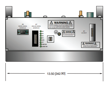
AC INPUT POWER J1 6 PIN CONNECTOR
| Pin | Signal | Parameters |
|---|---|---|
| 1 | Line | Line |
| 2 | Removed | N/C |
| 3 | Neutral | Neutral |
| 4 | Removed | N/C |
| 5 | Spare | N/C |
| 6 | Spare | N/C |
RS-232 DIGITAL INTERFACE— JB16 9 PIN FEMALE D CONNECTOR
| Pin | Signal | Parameters |
|---|---|---|
| 1 | N/C | No Connection |
| 2 | TD | Transmit Data |
| 3 | RD | Receive Data |
| 4 | N/C | No Connection |
| 5 | SGND | Signal Ground |
| 6 | N/C | No Connection |
| 7 | N/C | No Connection |
| 8 | N/C | No Connection |
| 9 | N/C | No Connection |
ANALOG INTERFACE— J7 7 PIN MOLEX CONNECTOR
| Pin | Signal | Parameters |
|---|---|---|
| 1 | Ex Gate | Low = X-Ray OFF, +12Vdc = X-Ray ON |
| 2 | Signal Ground | Ground |
| 3 | N/C | No Connection |
| 4 | kV Monitor | 0-9 Vdc = 0 to 100% rated output |
| 5 | Signal Ground | Ground |
| 6 | mA Monitor | 0 to 9Vdc = 0 to 100% rated output |
| 7 | Fault | Open collector, 35V @ 10mA max, High = No Fault |
LED INDICATORS
| Indicator | Signal Name | Condition Illuminated When... |
|---|---|---|
| LED 1 | OV | High kV occurs |
| LED 2 | UV | Low kV occurs |
| LED 3 | UC | Low mA occurs |
| LED 4 | OC | High mA occurs |
| LED 5 | ARC FLT | Arc fault occurs |
| LED 6 | OT | Over temperature occurs |
| LED 7 | X-RAY ON | X-Rays are enabled |
| LED 8 | PWR | Power is ON |
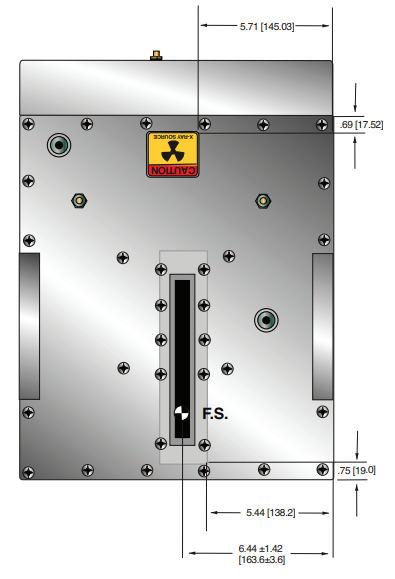
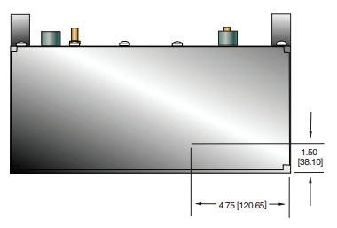
Tables & Diagrams
DIMENSIONS: in.[mm]
FRONT VIEW
TOP VIEW
BACK VIEW
SIDE VIEW
Frequently Asked Questions
Why Is Oil Insulation Used?
Do I Need to Ensure My Monoblock® Stays Cool? Why?
How Often Do I Need to Season My Monoblock® X-Ray Source? Why?
Application Notes AN-12 – The Benefit of Using a Current Source to Power X-Ray Tube Filament Circuits

