XMPF Series
- Output Voltage -20V to -10kV
- Integrated Floating Filament Supply
- Low Ripple
- Local and Remote Programming
- OEM Customization Available
*Note: All specifications are subject to change without notice. Please consult the English PDF version of this datasheet for the most up-to-date revision.


5W X-Ray Generator
The XMPF is a modular 10kV @ 5W X-Ray generator designed to drive a floating filament X-Ray tube via closed loop filamentary control of the 0 to 500uA emission current. The floating filament supply is rated at 0 to 0.42 amps @ 3.5Vac. The filament supply features an adjustable 0 to 0.42 amp filament limit.
The high voltage program and emission current program have internal preset capability simplify interfacing to this X-Ray generator. Alternatively, a customer provided 0 to 10Vdc signal can be used to remotely control these two signals. A high voltage monitor signal and emission current monitor signal is provided. Additionally a filament current monitor signal is also provided. A High Voltage Enable input provides control of the high voltage output.
Specifications
(Ref. 128131-001 REV. B)
Input Voltage:
+24 Vdc, ±10%
Input Current:
500mA maximum
Cathode Supply:
Voltage: 10kV, controllable over the range -20V to -10kV
Accuracy: <2%
Polarity: Negative
Line Regulation: <0.05% for input voltage change of ±10%
Load Regulation: <0.1% for zero to full load
Stability: <0.1% per 24 hours at constant operating conditions, after 30 minutes warm up
Temperature Coefficient: <250 ppm/˚C
Ripple: <0.01% p-p of output voltage at full voltage and current
Output Current Limit: 550μA ±10%
Ramp Rate: <20kV/sec
Current Characteristics:
Maximum Emission Current: 500uA
Operating: 5˚C to 40˚C
Stability: 0.5% using the internal reference and setting potentiometer. For increased stability an external reference can be used.
Environmental:
Humidity:
Operating: 20% to 80% RH, non-condensing
Storage: 5% to 95%
Filament Supply:
Voltage: 0V to 3.5Vac referenced to Cathode output
Load Current: 0.42A max, pre set adjustable limit
Stability: <0.1% over a 30 minute period at constant operating conditions.
Environmental:
Temperature Range:
Operating: 5˚C to 40˚C
Storage: -40˚C to 70˚C
High Voltage Output:
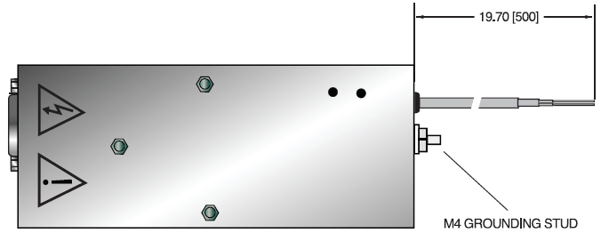
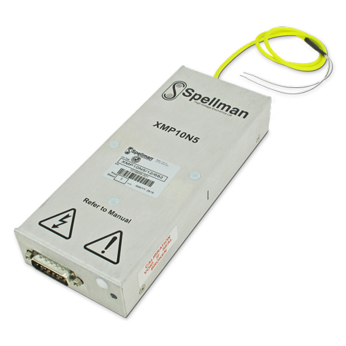
Flying leads, Reynolds 18kV rated FEP insulated wire, 1.02mm diameter. Conductors are 19/40 AWG. Overall length is 500mm,Flying leads, Reynolds 18kV rated FEP insulated wire, 1.02mm diameter. Conductors are 19/40 AWG. Overall length is 500mm, the two wires are sleeved together.
Dimensions:
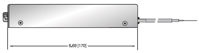
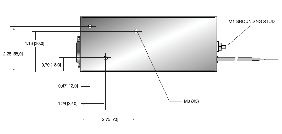
1.18”H x 2.75”W x 6.69”D (30mm x 70mm x 170mm)
Weight:
4.4 lbs. (2.0kg)
Regulatory Approvals:
Designed to meet IEC/UL 61010-1 Safety requirements for electrical equipment for measurement, control and laboratory use; CAN/CSA-C22.2 No.61010-1. CE marked to EN 61010-1. RoHS compliant.
As the unit is designed for incorporation within the users system it is not tested against any specific EMC standards. The user will need to take sensible EMC precautions when designing the unit in and verify the overall system EMC performance against any relevant standards.
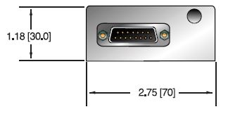
| PIN | SIGNAL | SIGNAL PARAMETERS |
|---|---|---|
| 1 | +24Vdc | +24Vdc @ 500mA, max. |
| 2 | Power Ground | Power Ground |
| 3 | N/C | N/C |
| 4 | Signal Ground | Signal Ground |
| 5 | HV Enable | 0-0.8V = HV ON, 2.4V-12V = HV OFF |
| 6 | N/C | N/C |
| 7 | HV Program Output | 0-10V from pre-set potentiometer. See note below. |
| 8 | HV Program Input | 0-10Vdc = 0-10kV, Zin = 470kΩ, accuracy ±2% of FS |
| 9 | High Voltage Monitor | 0-10Vdc = 0-10kV, Zout = 2.2kΩ, accuracy ±2% of FS |
| 10 | Emission Current Monitor | 0-10Vdc = 0-500uA, Zout = 2.2kΩ, accuracy ±3% of FS |
| 11 | Filament Current Monitor | 0-10Vdc = 0-500mA, Zout = 2.2kΩ, accuracy ±5% of FS |
| 12 | Emission Current Program Input |
0-10Vdc = 0-500uA, Zin = 10MΩ, accuracy ±3% of FS |
| 13 | Emission Current Program Output |
0-10V from pre-set potentiometer. See note below. |
| 14 | Signal Ground | Signal Ground |
| 15 | Filament Current Limit | 0-10V = 0-0.42A from pre-set potentiometer. See note below. |
The pre-set potentiometers are accessible through the side of the case.
To pre-set the filament current limit, adjust the potentiometer (indicated "Preset fil max" on the case).
If external programming is not required:
To pre-set the HV, adjust the potentiometer (indicated RV4 on the case) to desired value, and link pins 7 and 8.
To pre-set the emission current, adjust the potentiometer (RV3), and link pins 12 and 13.
| How to Order: |
|---|
| Model number: XMPF10N5/24 |