EBM-TEG
- Triode Supply for Thermionic Emission SEM
- High Precision, Low Noise, Ultra Stable
- Over Current/Voltage Protection
- OEM Customization Available
- UL, CE and RoHS Compliant
*Note: All specifications are subject to change without notice. Please consult the English PDF version of this datasheet for the most up-to-date revision.


Triode Supply for Thermionic SEM
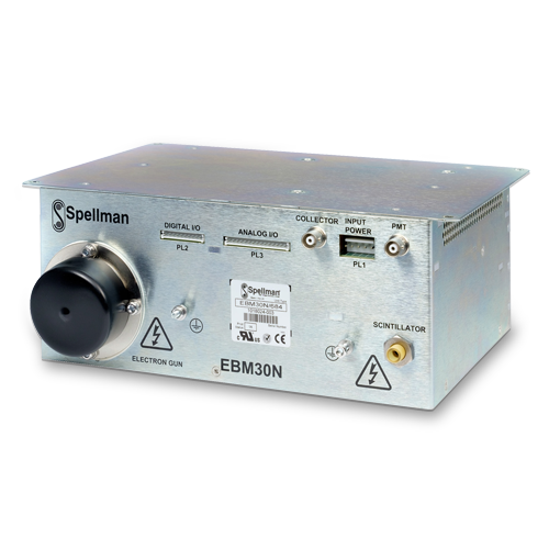
The EBM30N/TEG is an integral solution that provides the high voltage required by Thermionic Emission Scanning Electron Microscope (SEM). Spellman’s proprietary packaging and encapsulation technology gives dramatic improvements in size, cost and performance compared to other SEM power supply offerings.
This unit provides a highly regulated, low noise, ultra-stable Accelerator supply programmable from 0 to -30kV at 170uA, together with Floating Filament and Bias supplies referenced to the Accelerator to control the beam. The unit also includes high voltage outputs to drive the Detector, comprising PMT, Scintillator and Collector grounded outputs.
Programming signals utilize differential analog inputs to minimize external noise and offset voltages effects. A ground referenced emission current monitor and a filament failure signal are provided.
Specifications
(Ref. 128031-001 REV. A)
SPECIFICATIONS
Input Voltage:
+24Vdc, ±5% @ 2.5A max.
Scintillator Output:
Custom ’Poke home’ receptacle manufactured by Spellman. For mating cables, see HOW TO ORDER information below.
PMT and Collector Outputs:
Industry standard BNC.HT receptacle: Radiall R316 553
Temperature:
Operating: 0°C to +45°C
Storage: -20°C to +75°C
Humidity:
0 to 85% RH, non-condensing
Dimensions:
4.13˝ H x 9.85˝ W x 7.48˝ D (105mm x 250mm x 190mm) excluding the top mounting bracket
Weight:
16.5 lbs. (7.5kg)
Regulatory Approvals:
UL recognized component (RC). File number E354595. Compliant to IEC/UL 61010-1 Safety requirements for electrical equipment for measurement, control and laboratory use; CAN/CSA-C22.2 No.61010-1. CE marked to EN 61010-1. UKCA marked to BS EN 61010-1. RoHS compliant. (As the unit is designed for incorporation within the users system it is not tested against any specific EMC standards. The user will need to take appropriate EMC precautions when designing the unit in and verify the overall system EMC performance against any relevant standards.)
OUTPUT SPECIFICATIONS
| Output | Accelerator (Internal Supply) |
Bias Cancellation (Internal Supply) |
Filament | PMT | Scintillator | Collector |
|---|---|---|---|---|---|---|
| Output Voltage | 0 to -30kV, referenced to ground | 0 to +3.5kV referenced to Accelerator* | -1.936 to +1.936V referenced to Accelerator | 0 to -1300V referenced to ground | +8kV to +11kV referenced to ground | 30V to 500V referenced to ground |
| Output current - max | 170μA | 150μA |
3.87A | 1mA (current trip level: 1.2mA) | 250μA | 5mA |
| Accuracy | ±2% or ±20V (whichever is greater) | ±10% or ±180V (whichever is greater) | 0.1V | ±2% or ±1V (whichever is greater) | ±2% | ±5% |
| Load Regulation | <100ppm for 0 to 170μA | N/A | <2% for 10% change in load resistance | <100ppm for 0 to 1mA | <500ppm for 0 to 250μA | <5% for 0 to 5 mA |
| Line Regulation for a ±5% line change | <100ppm | <0.1% | <1% | <100ppm | <500ppm | <5% |
| Ripple p-p at max output | <20ppm | <5ppm | <0.1% | <200mV | <0.1% | <0.2% |
| Temperature Coefficient | <100 ppm/°C | <1000 ppm/°C | <300 ppm/°C | <1000 ppm/°C | <100 ppm/°C | <1000 ppm/°C |
| Stability (1hr warm up) | 8ppm/3min | 1%/10min | 100ppm/10min | 200ppm/1h | 500ppm/8h | <1500ppm/1h |
| Rise time (switch on) | 1 to 3s (0 to 90%) | <1s (0 to 90%) | 250ms (0 to 90%) | <1s (0 to 90%) | <1s (0 to 90%) | <1s (0 to 90%) |
| Fall time (switch off) | <100s (to < 50V) | <100s (to < 50V) | <0.5s (100% to 10%) | <10s (to < 50V) | <10s (to < 100V) | <10s (to < 50V) |
*The positive Bias Cancellation voltage reduces the negative Bias output, allowing the emission current to flow (see User Guide for more information).
PL1 INPUT POWER CONNECTOR JST MODEL B 5PS-VH
| Pin | Signal | I/O | Signal Parameters | Remarks |
|---|---|---|---|---|
| 1 | +24V | I | DC24V Input | Pins connected internally |
| 2 | +24V | I | DC24V Input | Pins connected internally |
| 3 | 0V | I | DC24V Common | Pins connected internally |
| 4 | 0V | I | DC24V Common | Pins connected internally |
| 5 | FG | - | Case Ground | Internally connected to 0V |
PL2 DIGITAL I/O CONNECTOR JST MODEL S10B-EH
| Pin | Signal | I/O | Signal Parameters |
|---|---|---|---|
| 1 | Remote on/off | I | Outputs 1,2 and 3 (Acc., Bias, Fil.) remote on/off. High = off |
| 2 | Remote 4 on/off | I | P.M.T remote on/off. High = off |
| 3 | Remote 5 on/off | I | Scintillator remote on/off. High = off |
| 4 | Remote 6 on/off | I | Collector remote on/off. High = off |
| 5 | Remote signal gnd | I | 0V connection for remote controls |
| 6 | Filament open cct | O | High = failed |
| 7 | Filament OC return | O | 0V |
| 8 | N/C | - | N/C |
| 9 | N/C | - | N/C |
| 10 | N/C | - | N/C |
PL3 ANALOG I/O CONNECTOR JST MODEL S15B-EH
| Pin | Signal | I/O | Parameters |
|---|---|---|---|
| 1 | Fil Prog (+) | I | 0 to 4V differential input = 0 to 4V Filament output |
| 2 | Fil Prog (-) | I | 0 to 4V differential input = 0 to 4V Filament output |
| 3 | Bias Cancel Prog (+) | I | 0 to 3.5V differential input = 0 to 3.5kV Bias Cancellation output |
| 4 | Bias Cancel Prog (-) | I | 0 to 3.5V differential input = 0 to 3.5kV Bias Cancellation output |
| 5 | Acc Prog (+) | I | 0 to 6V differential input = 0 to -30kV Accelerator output |
| 6 | Acc Prog (-) | I | 0 to 6V differential input = 0 to -30kV Accelerator output |
| 7 | EMS Monitor | O | Emission Current Monitor Output. 0 to 10V = 0 to 200μA Limited to 12V max. ±3% or 0.1V, whichever is greater |
| 8 | EMS Mon 0V | O | Emission Current Monitor Output. 0 to 10V = 0 to 200μA Limited to 12V max. ±3% or 0.1V, whichever is greater |
| 9 | PMT Prog (+) | I | 0 to 6.5V differential input = 0 to 1300V P.M.T output |
| 10 | PMT Prog (-) | I | 0 to 6.5V differential input = 0 to 1300V P.M.T output |
| 11 | Scintillator Prog (+) | I | 0 to 5.5V differential input = 0kV to 11kV Scintillator output |
| 12 | Scintillator Prog (-) | I | 0 to 5.5V differential input = 0kV to 11kV Scintillator output |
| 13 | Collector Prog | I | 0 to 5V differential input = 0 to 500V Collector output |
| 14 | Collector Prog 0V | I | 0 to 5V differential input = 0 to 500V Collector output |
| 15 | N/C | - | N/C |
HOW TO ORDER
| Description | Part Number |
|---|---|
| EBM-TEG | EBM30N/TEG |
| Low voltage mating connectors accessory Kit | 13802-27 |
| HV Out Cable - 2 meters | HVC30/3SO/1317 |
| HV Out Cable - 3 meters | HVC30/3SO/1314 |
| HV Out Cable - 5 meters | HVC30/3SO/1315 |
| Scintillator Cable - 1 meter | HVC11/1SO/1320 |
| Scintillator Cable - 2 meters | HVC11/1SO/1316 |
Tables & Diagrams
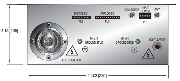
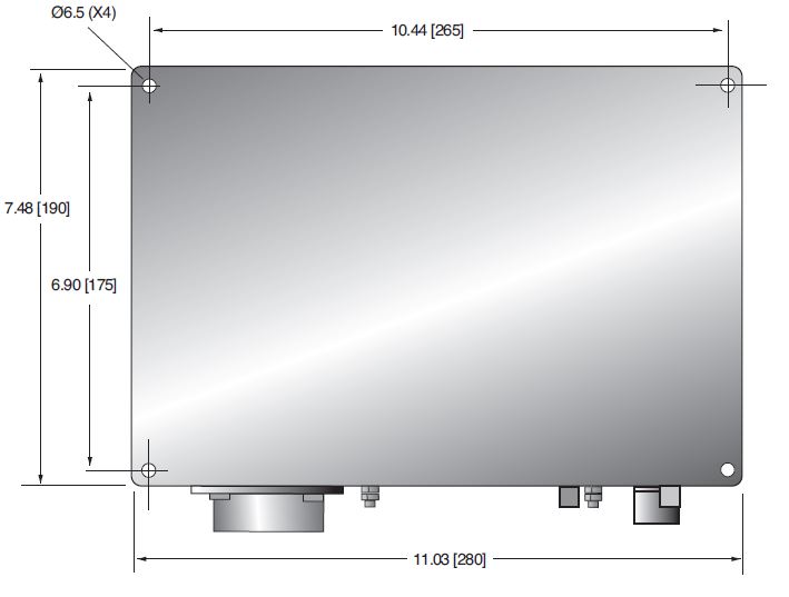
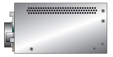
DIMENSIONS: in.[mm]
FRONT VIEW
TOP VIEW
SIDE VIEW
Note: An accessory kit which contains the mating housings and crimps for the low voltage connectors is available to order free of charge. See HOW TO ORDER table.