")
UMW Series
- Voltage from 8kV to 20kV, Fixed Negative or Positive Polarity
- Output Power of 60 and 125 Watts
- V/I Regulation with Automatic Crossover Control
- Voltage and Current Monitor Signals
- UL Recognized, CE Listed and RoHS Compliant
*Note: All specifications are subject to change without notice. Please consult the English PDF version of this datasheet for the most up-to-date revision.

![]()

60-125W High Voltage Power Supplies
Form, Fit and Function Usability:
Spellman’s UMW Series of high voltage modules provides users with a form, fit and function replacement for presently available commercially made units, while providing superior features and benefits at competitive pricing. Utilizing proprietary power conversion technology, unique high voltage packaging, and Spellman’s unmatched encapsulation techniques, these SMT based high voltage modules provide improved performance and easier system integration at a lower cost when compared to the competition.
Advanced Power Conversion Topology:
UMW converters use a proprietary resonant power conversion topology providing exceptional efficiency and inherent low noise and ripple outputs. Radiated emissions are dramatically reduced compared to conventional switching topologies, effectively minimizing or even eliminating the need to shield the unit from adjacent circuitry.
The high voltage output is generated through the use of a ferrite core high voltage step up transformer which feeds the high voltage output circuitry. Units utilize an appropriate arrangement of low capacitance Cockcroft-Walton voltage multiplier stages to obtain the specified high voltage output.
Due to the fixed, high frequency conversion rate of the converter, the output capacitance is small resulting in minimal stored energy and fast rise times. Through the use of generously rated surge limiting resistors and a fast acting current loop, all units are fully arc and short circuit protected.
Control and Regulation:
The actual output voltage generated is sampled via a high impedance divider to create a voltage feedback signal. A current feedback signal is created via a current sense resistor being placed in the low end return of the high voltage output circuitry. These two accurate ground referenced feedback signals are used to precisely regulate and control the units output. These accurate and calibrated signals are also used for external monitoring purposes.
Due to the UMW’s unique converter topology it can provide full current into low impedance loads or even a short circuit. Standard units limit at 103% of maximum rated output current.
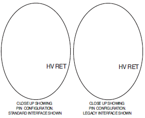
Standard User Interface:
The Spellman UMW Series offers a standard customer interface that provides current programming capability and positive polarity, buffered, low output impedance voltage and current monitor signals (0 to +4.64Vdc equals 0 to full scale rated). A voltage programming input is provided where 0 to +4.64Vdc equals 0 to 100% of rated voltage.
Current programmability allows the user to set where the unit will current limit, anywhere from 0 to 100% of maximum rated current. This feature is beneficial where less than full output current is desired, like in the case of protecting a sensitive load.
The buffered low impedance voltage and current monitor signals can drive external circuitry directly, while minimizing loading and pickup effects. These feature save the user the expense and implementation of external interface buffering circuitry while improving overall signal integrity.
Mechanical and Environmental Considerations:
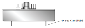
The UMW Series are modular sheet metal enclosed converters measuring 8.00. X 4.50. X 1.075. (203mm X 114mm X 27mm). All units are encapsulated using a propriety silicon based potting material which is considerably lighter in weight than epoxy encapsulation techniques. Physical mounting of the unit is accomplished via the use of bottom mounted studs or threaded blind inserts, dependent upon model ordered.
Specifications
(Ref. 128070-001 REV. M)
Input Voltage:
24Vdc
Normal Voltage Range:
23Vdc to 30Vdc
Derated Voltage Range:
11Vdc to 30Vdc
Input Current: (typical)
Disabled: <40mA
No load: <600mA
Full load: 60 watt units: 3 amps
125 watt units: 6.2 amps
Voltage Regulation:
Line: <0.01%
Load: <0.01%
Current Regulation:
Line: <0.01%
Load: <0.01%
Stability:
0.01% per 8 hours, 0.02% per day after 30 min. warmup
Accuracy:
2% on all programming and monitoring, except I Sense 10%
Temperature Coefficient: (typical)
100ppm/°C
Overshoot:
<0.1% Vp
Environmental:
Temperature Range:
Operating: 0°C to 65°C case temperature
Storage: -55°C to 85°C, non operational
Humidity:
10% to 90%, non-condensing
Dimensions:
8.00. L X 4.50. W X 1.075. H (203mm X 114mm X 27mm)
Weight:
1.75 lbs. (0.79kg)
Regulatory Approvals:
Compliant to EEC EMC Directive. Compliant to EEC Low Voltage Directive. UL/CUL recognized, File E227588. RoHS Compliant.
See product PDF for more specification and features.
UMW 60W SELECTION TABLE
| Model Number | Output V | Output Current | Ripple(max) %Vp-p | Output Capacitance | Arc Limiting Resistance | I Sense Scaling Full Scale Signal | |
|---|---|---|---|---|---|---|---|
| UMW8*60 | 0 to 8kV | 7.5mA | <1.0 (C load ≥0.05μF | 3553pF | 14.1kΩ | 1.6V | |
| UMW10*60 | 0 to 10kV | 6mA | <1.0 (C load ≥0.05μF | 3553pF | 14.1kΩ | 1.47V | |
| UMW12*60 | 0 to 12kV | 5mA |
|
2870pF | 30kΩ | 1.24V | |
| UMW15*60 | 0 to 15kV | 4mA | <1.0 (C load ≥0.05μF | 2460pF | 30kΩ | 1.0V | |
| UMW20*60 | 0 to 20kV | 3mA | <1.0 (C load ≥0.01μF) | 2460pF | 45kΩ | 4.61V |
UMW 125W SELECTION TABLE
| Model Number | Output V | Output Current | Ripple(max) %Vp-p | Output Capacitance | Arc Limiting Resistance | I Sense Scaling Full Scale Signal |
|---|---|---|---|---|---|---|
| UMW8*125 | 0 to 8kV | 15.5mA | <1.0 (C load ≥0.05μF | 7106pF | 3kΩ | Signal 1.1V |
| UMW10*125 | 0 to 10kV | 12.5mA | <1.0 (C load ≥0.05μF | 7106pF | 3kΩ | 1.15V |
| UMW12*125 | 0 to 12kV | 10.5mA | <1.0 (C load ≥0.05μF | 5740pF | 6.6kΩ | 1.40V |
| UMW15*125 | 0 to 15kV | 8.3mA | <1.0 (C load ≥0.05μF | 4920pF | 6.6kΩ | 1.1V |
| UMW20*125 | 0 to 20kV | 6.25mA | <1.0 (C load ≥0.01μF | 4920pF | 14.1kΩ | 9.57V |
Grayed text indicates Legacy interface signals.
ORDERING INFORMATION
| Voltage | |
|---|---|
| 0 to 8kV | 8 |
| 0 to 10kV | 10 |
| 0 to 12kV | 12 |
| 0 to 15kV | 15 |
| 0 to 20kV | 20 |
| Polarity | |
| Positive | P |
| Negative | N |
| Power | |
| 60 Watts | 60 |
| 125 Watts | 125 |
| Legacy Interface | |
| Legacy Interface | L |
If a high voltage mating connector is required it should be included at time of order. See page 3 for details.
STANDARD INTERFACE
| Pin | Signal | Parameters |
|---|---|---|
| 1 | Power Ground Return | +24Vdc power ground return |
| 2 | + Power Input | +24Vdc power input |
| 3 | I Sense | See I Sense text and tables for details |
| 4 | Enable Input | Low (<0.7V, Isink@1mA)=HV OFF, High (open or >2V)=HV ON |
| 5 | Signal Ground | Signal Ground |
| 6 | Remote V Adjust | 0 to +4.64Vdc = 0 to 100%, Zin >1MΩ |
| 7 | +5V Reference Output | +5Vdc ±2%. Zout = 475Ω |
| 8 | Power Ground Return | +24Vdc Power Ground Return |
| 9 | + Power Input | +24Vdc Power Input |
| 10 | Signature Resistor | Unique identifying resistor connected to ground |
| 11 | Remote I Adjust | 0 to +4.64Vdc = 0 to 100%, Zin >1MΩ Leave open for preset current limit @103% of rated output current |
| 12 | I Monitor | 0 to +5Vdc = 0 to 107.5%, Zout <10kΩ |
| 13 | V Monitor | 0 to +5Vdc = 0 to 107.5%, Zout <10kΩ |
| 14 | E Out Monitor | 1.00 Volt, 1GΩ/1.1MΩ divider with 10MΩ meter |
LEGACY INTERFACE (L OPTION)
| Pin | Signal | Parameters |
|---|---|---|
| 1 | Power Ground Return | +24Vdc power ground return |
| 2 | + Power Input | +24Vdc power input |
| 3 | I Sense | See I Sense text and tables for details |
| 4 | Enable Input | Low (<0.7V, Isink@1mA)=HV OFF, High (open or >2V)=HV ON |
| 5 | Signal Ground | Signal Ground |
| 6 | Remote Adjust | Positive Polarity Unit: 0 to +4.64Vdc = 0 to 100% rated voltage Zin>1MΩ Negative Polarity Unit: +5Vdc to 0.36Vdc = 0 to 100% rated voltage Zin>1MΩ |
| 7 | +5V Reference Output | +5Vdc ±2%. Zout = 475Ω |
| 8 | Power Ground Return | +24Vdc Power Ground Return |
| 9 | + Power Input | +24Vdc Power Input |
| 10 | Signature Resistor | Unique identifying resistor connected to ground |
| 11 | N/C | |
| 12 | N/C | |
| 13 | N/C | |
| 14 | E Out Monitor | 1.00 volt/kV, 1GΩ/1.1MΩ divider with 10MΩ meter |
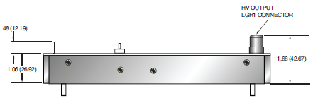
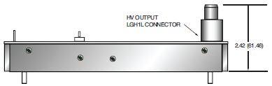
HIGH VOLTAGE MATING CONNECTOR
| kV | CONNECTOR |
|---|---|
| 8 | LGH1 SHV P.N. 304781-001 |
| 10 | LGH1 SHV P.N. 304781-001 |
| 12 | LGH1 SHV P.N. 304781-001 |
| 15 | LGH1 SHV P.N. 304781-001 |
| 20 | LGH1L SHV P.N. 304781-101 |
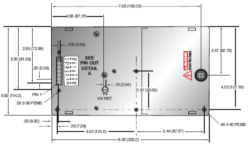
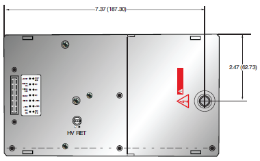
Tables & Diagrams
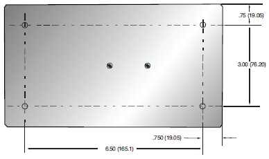
DIMENSIONS: in.[mm]
TOP VIEW
UMW UP TO 15KV
BOTTOM VIEW
SIDE VIEW
FRONT VIEW
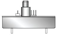
TOP VIEW
UMW 20KV
PIN OUT
DETAIL A
ALL UMW UNITS
SIDE VIEW
UMW 20KV
FRONT VIEW
UMW 20KV
Frequently Asked Questions
What Is a Safe Level of High Voltage?
Where Can I Obtain Information on High Voltage Safety Practices?
What Kind of High Voltage Connector Do You Use on Your Supplies?
What Do You Mean That the Output Side of the High Voltage Cable on Most Standard Products Is “Unterminated”?
How Should I Ground Your Supply?
Why Is Arcing an Issue for a High Voltage Power Supply?

