")
MPS Series
- Differential Input for Voltage Program
- Optional RS-232/RS-485 Control
- Voltage and Current Monitors and Controls
- High Stability, Ultra Low Ripple and Noise
- CE Marked and UL61010-1 Certified
*Note: All specifications are subject to change without notice. Please consult the English PDF version of this datasheet for the most up-to-date revision.
![]()
10W DC-DC High Voltage Power Supplies
Spellman’s new MPS series are a family of high voltage 10 Watt modules that provide output voltages ranging from 1kV to 30kV.
The MPS series are high performance products designed with Spellman’s hybrid topology of linear and switch mode power conversion techniques delivering lower noise with higher efficiency. The MPS series produces excellent ripple and stability performance specifications from a compact footprint. Additionally the MPS series features, as standard, a differential amplifier input for the voltage programming signal to improve immunity from external system noise and addressing any offset issues. Alternatively the output voltage may be pre-set by an internal potentiometer.
RS-232 or RS-485 digital interfaces are also available as optional; both the standard analog and the optional digital controls are provided via a 15-pin D-type connector.
Spellman’s proprietary HV technology coupled with SMT circuitry results in an ultra compact and lightweight module that is available as either a positive or negative supply that is ideal for OEM applications.
Typical Applications:
- Photomultiplier Tubes
- Electrostatic Printing
- Electron and Ion Beams
- Scintillators
- Electronmultiplier Detectors
- Microchannel Plate Detectors
- Mass Spectrometry
- Nuclear Instruments
- Electrostatic Lenses
Specifications
(Ref. 128033-001 REV. T)
Input Voltage:
+24 Vdc, ±2Vdc
Input Current:
≤ 1 amp maximum
Output Voltage:
9 models available from 1kV to 30kV
Output Polarity:
Positive or negative, specify at time of order
Power:
10 watts, maximum
Voltage Regulation:
Line: ≤ 0.001% of rated output voltage over specified input voltage
Load: ≤ 0.001% of rated output voltage for full load change
Current Regulation (VCC Option):
Line: ≤ 0.01% for 1V input voltage change under any load conditions
Load: ≤ 0.01% for full load to short circuit
Ripple:
See “model selection” table
Stability:
≤ 0.007% per hour, 0.02% per 8 hours after 1.0 hour warm up period.
≤ 0.05% per 1000 hours after 1.0 hour warm up period (HS option)
Temperature Coefficient:
≤ 25ppm per degree C
≤ 10ppm per degree C (HS option)
Environmental:
Temperature Range:
Operating: 0°C to 50°C
Storage: -35°C to 85°C
Humidity:
20% to 85% RH, non-condensing
Cooling:
Convection cooled
Dimensions:
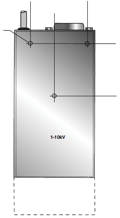
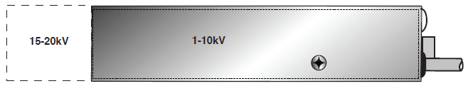
1-10kV: 1.18. H X 2.75. W X 5.12. D (30mm x 70mm x 130mm)
15-20kV: 1.18. H X 2.75. W X 6.49. D (30mm x 70mm x 165mm)
30kV: 1.37. H X 2.95. W X 8.47. D (65mm x 75mm x 215mm)
Weight:
1-3kV: 9.88 oz. (280g)
5-10kV: 14.82 oz. (420g)
15-20kV: 22.92 oz. (650g)
30kV: 35.51 oz. (950g)
Interface Connector:
15 pin male D connector
Output Connectors:
A captive 39.4˝ (1 meter) long shielded HV cable is provided
Regulatory Approvals:
UL recognized component (RC), File E354595. Compliant to EC/UL 61010-1 Safety requirements for electrical equipment for measurement, control and laboratory use; CAN/CSA-C22.2 No.61010-1. CE marked to EN 61010-1. UKAS marked to BS EN 61010-1. RoHS compliant.
As the unit is designed for incorporation within the users system it is not tested against any specific EMC standards. The user will need to take sensible EMC precautions when designing the unit in and verify the overall system EMCperformance against any relevant standards.
Options:
VCC - Variable Current Control
HS - High Stability
DCC 2 - RS-232
DCC 4 - RS-485
Note: It is not possible to supply the unit with both full HS and DCC options
MPS ANALOG INTERFACE— 15 PIN D CONNECTOR (NON-DCC UNITS)
| Pin | Signal | Signal Parameters |
|---|---|---|
| 1 | Power/Signal Ground | Ground (also used as analog signal ground on 1kV to 10kV units) |
| 2 | +24Vdc Input | +24Vdc @ 1 amp maximum |
| 3 | Voltage Monitor Output | 0 to 10Vdc=0 to 100% Rated Output ±2%, Zout =10kΩ |
| 4 | Local Programming Potentiometer Wiper Output | Potentiometer connected to +10Vdc (accuracy: 0.2%) and ground, 0 to 10Vdc adjustable wiper output provided |
| 5 | Voltage Program Input | 0 to 10Vdc=0 to 100% Rated Output ±2%, Zin=10MΩ |
| 6 | Voltage Program Differential Amplifier Output | 0 to 10Vdc=0 to 100% Rated Output, Zout =10kΩ |
| 7 | Voltage Program Differential Amplifier Input—Positive | 0 to 10Vdc differential between pin 7 and pin 9 = 0 to 100% of rated output, diode clamped to ground, Zin =38kΩ |
| 8 | Current Monitor Output | 0 to 10Vdc = 0 to 100% Rated Output ±2%, Zout =10kΩ |
| 9 | Voltage Program Differential Amplifier Input—Negative | 0 to 10Vdc differential between pin 7 and pin 9 = 0 to 100% of Rated Output, diode clamped to ground, Zin =38kΩ |
| 10 | No Connection | No Connection |
| 11 | Current Program Input | Standard: Internally connected to provide 110% fixed current limit VCC Option: 0 to 10Vdc=0 to 100% Rated Output ±2%, Zin=1MΩ |
| 12 | Enable Input | Low = Enable, TTL, CMOS, Open Collector Compliant |
| 13 | Internal Connection | No Connection |
| 14 | Vref (/HS unit only) | +10V ultra high stability reference output. Accuracy: 0.05%, temperature coeff. <5ppm/°C On standard units the reference voltage is available on pin 4 |
| 15 | Analog Signal Ground (15kV to 20kV units) | Analog Signal Ground (No connection for (1kV to 10kV units) |
MPS DIGITAL INTERFACE— 15 PIN D CONNECTOR (DCC UNITS)
| Pin | Signal | Signal Parameters |
|---|---|---|
| 1 | Power/Signal Ground | Ground |
| 2 | +24Vdc Input | +24Vdc @ 1 amp maximum |
| 3 | No Connection | No Connection |
| 4 | Local Programming Potentiometer Wiper Output | Potentiometer connected to +10Vdc and Ground, 0 to 10Vdc adjustable wiper output provided |
| 5 | No Connection | No Connection |
| 6 | No Connection | No Connection |
| 7 | No Connection | No Connection |
| 8 | No Connection | No Connection |
| 9 | No Connection | No Connection |
| 10 | No Connection | No Connection |
| 11 | No Connection | No Connection |
| 12 | Enable Input | Low = Enable, TTL, CMOS, open collector compliant |
| 13 | No Connection | No Connection |
| 14 | TxD | Transmit data (output) with respect to ground (pin 1) |
| 15 | RxD | Receive data (input) with respect to ground (pin 1) |
Notes: 1.) The DCC option operated via a simple ASCII protocol. Contact us for more information.
2.) The HS and DCC option cannot be offered together
MPS SELECTION TABLE
| Model | Output Voltage | Output Current | Ripple (Vpp) |
|---|---|---|---|
| MPS1*10/24 | 1kV | 10mA | <10mV |
| MPS2*10/24 | 2kV | 5.00 mA | <20mV |
| MPS2.5*10/24 | 2.5kV | 4.00 mA | <25mV |
| MPS3*10/24 | 3kV | 3.3mA | <25mV |
| MPS5*10/24 | 5kV | 2mA | <30mV |
| MPS10*10/24 | 10kV | 1mA | <50mV |
| MPS15*10/24 | 15kV | 0.66mA | <100mV |
| MPS20*10/24 | 20kV | 0.5mA | <150mV |
| MPS30*10/24 | 30kV | 0.33mA | <250mV |
*Specify “P” for positive polarity or “N” for negative polarity. Custom units available.
| How To Order: | |||
|---|---|---|---|
| MPSXX*10/24/YYY where: XX is the Output voltage (see selection table) * is the polarity: P for positive / N for negative YYY is the option: VCC / HS / DCC2 / DCC4 |
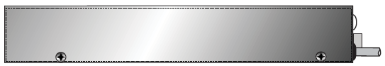
Tables & Diagrams
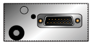
DIMENSIONS: in.[mm]
1-20kV
FRONT VIEW
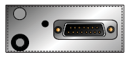
BOTTOM VIEW
SIDE VIEW
30kV
FRONT VIEW
BOTTOM VIEW
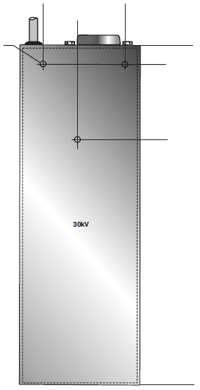
SIDE VIEW