")
CZE2000
- Cost Effective Modular Supply; Ideal for Electrospinning
- 0-30kV. 0-300µA; Local or Remote Programmable
- Polarity Reversible Upon Command in <1 Sec at No Load
- Low Stored Energy, Current Limited Output
*Note: All specifications are subject to change without notice. Please consult the English PDF version of this datasheet for the most up-to-date revision.


CZE2000 Auto-Reversing Modular High Voltage Power Supply
Spellman’s CZE2000 modular high voltage power supply is ideal for OEM usage. It is specifically designed to meet the needs of applications requiring a hot switched reversible output voltage. The output polarity of the unit can be quickly and safely reversed via the Polarity Control Signal provided on the interface connecter.
Both the output voltage and current are fully adjustable via ground referenced remote programming signals such that 0 to 10Vdc corresponds to 0 to 100% rated output voltage and current.
Remote motioning functionality is provided by voltage and current test points such that 0 to 10Vdc corresponds to 0 to 100% rated voltage and current. Additionally remote polarity and mode indicators provide a comprehensive overview of power supply operation.
Excellent load and line regulation specifications along with outstanding stability and low ripple assure a stable high voltage output for consistent process results.
Typical applications:
- Electrospinning
- Mass Spectrometry
- Capillary Electrophoresis
- Electrostatic Research
Specifications
(Ref. 128076-001 REV. L)
Input Voltage:
24Vdc, ±10%
Input Current:
Less than 1 amp
Efficiency:
75% typical
Output Voltage:
See selection table
Output Current:
See selection table
Polarity:
Auto reversible via command
Power:
10 watts, maximum
Line Regulation:
0.01% for a 10% input voltage change
Load Regulation:
0.01% for a full load change
Ripple:
0.1% Vp-p
Stability:
0.02% per 8 hours (after 1/2 hr warmup)
NL Time Constant:
100ms
Stored Energy:
0.2 Joules at 30kV
Temperature Coefficient:
100ppm/°C
Operating Temperature:
0°C to 40°C
Storage Temperature:
-40°C to 85°C
Humidity:
10% to 85% RH, non condensing
Cooling:
Convection cooled
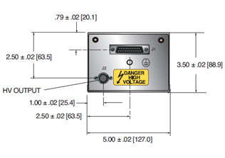
Dimensions:
3.5”H x 5”W x 10”D (8.9cm x 12.7cm x 25.4cm).
Weight:
6.2lbs. (2.8kg)
Interface Connector:
25 pin male D connector
HV Output Connector:
Detachable 36. (0.91m) cable provided
Regulatory Approvals:
Compliant to EEC EMC Directive. Compliant to EEC Low Voltage Directive. UL/CUL recognized file E148969. RoHS Compliant.
CZE2000 SELECTION TABLE
| Maximum Rating | Model Number | |
|---|---|---|
| kV | mA | |
| 5 | 2.0 | CZE5PN2000 |
| 10 | 1.0 | CZE10PN2000 |
| 15 | 0.67 | CZE15PN2000 |
| 20 | 0.50 | CZE20PN2000 |
| 30 | 0.30 | CZE2000 |
CZE2000 25 PIN MALE D CONNECTOR
| Pin | Signal | Parameters |
|---|---|---|
| 1 | +24Vdc Return | Power Return |
| 2 | +24Vdc Return | Power Return |
| 3 | +24Vdc Return | Power Return |
| 4 | HV Enable/Inhibit | Open or <1Vdc = HV OFF, >3.4Vdc (up to 15Vdc) = HV ON1 |
| 5 | Voltage Test Point | 0 to 10Vdc = 0 to 100% rated output, Zout =10kΩ, 1% |
| 6 | Current Test Point | 0 to 10Vdc = 0 to 100% rated output, Zout =10kΩ, 1% |
| 7 | Chassis Ground | Ground |
| 8 | Remote Voltage Control | 0 to 10Vdc = 0 to 100% Rated Output, Zin =10MΩ |
| 9 | Remote Current Control | 0 to 10Vdc = 0 to 100% Rated Output, Zin =10MΩ |
| 10 | +10Vdc Reference Output | +10Vdc, 4mA maximum |
| 11 | Signal Return | Signal Return |
| 12 | Polarity Control | Open or >3.4Vdc (up to 15Vdc) = Positive Polarity. Grounded or <1Vdc = Negative Polarity |
| 13 | Positive Polarity Indicator | +24Vdc sourced through a 100Ω series limiting resistor. +24Vdc = active signal |
| 14 | +24Vdc Input | Power Input |
| 15 | +24Vdc Input | Power Input |
| 16 | Chassis Ground | Ground |
| 17 | Negative Polarity Indicator | +24Vdc sourced through a 100Ω series limiting resistor. +24Vdc = active signal |
| 18 | I Mode Indicator | Open collector pulled up internally to +15Vdc through 2.7kΩ resistor with a 470Ω limiting resistor in series. Transistor OFF = signal active |
| 19 | V Mode Indicator | Open collector pulled up internally to +15Vdc through 2.7kΩ resistor with a 470Ω limiting resistor in series. Transistor OFF = signal active |
| 20 | Return Current Test Point | 0 to 10Vdc = 0 to 100% rated output current, as measured returned from load. Zout =10kΩ, 1% |
| 21 | Load Return | High Voltage Return Point. Required for GFI circuit functionality |
| 22 | Ground Fault Indicator | Open collector pulled up internally to +15Vdc through 4.7kΩ resistor with a 470Ω limiting resistor in series. Transistor OFF = signal active |
| 23 | Spare | No Connection |
| 24 | Spare | No Connection |
| 25 | Spare | No Connection |
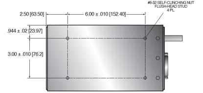
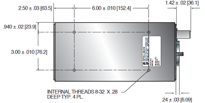
Tables & Diagrams
DIMENSIONS: in.[mm]
FRONT VIEW
TOP VIEW
BOTTOM VIEW
Frequently Asked Questions
What Is a Safe Level of High Voltage?
Where Can I Obtain Information on High Voltage Safety Practices?
How Should I Ground Your Supply?

