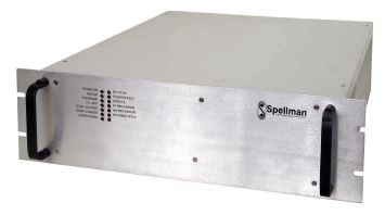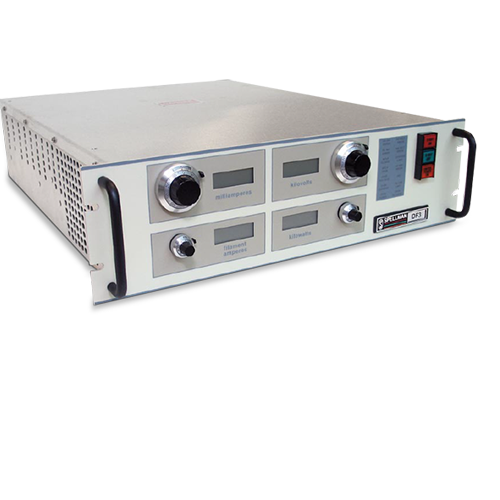
DF/FFシリーズ
- 通常のXRDおよびXRF X線管に最適
- 通常のXRDおよびXRF X線管用
- コンパクト、5 1/4” (3U) 高シャーシ
- 固形カプセル化で メンテナンス不要の運転をお約束
- HV照射電流はプリセット値まで自動上昇
- OEMカスタム化可能
*注: すべての仕様は予告なく変更される場合があります。最新版についてはこのデータシートの英語PDF版をご覧ください。

![]()
DF/FF シリーズ 3-4kW 産業用 X線発生器 | スペルマン高電圧電源
3kW/4kW X線発生器は電力スイッチ用IGBTを備えた最新イ ンバータ設計で、最新レベルの信頼性を提供します。再設計され たDF/FFの内部フィラメント電源は、より高い周波数での動作 によって、通常使用時でも低周波ノイズを除去します。DF/FF はサイン波電流源を使用しています。そのサイン波電流は 20kHz以上のスイッチング周波数で位相シフトする直列共振回 路により発生します。
この技術は、スイッチングや電力制御レギュレータにより通常 発生する好ましくない電磁波を除去します。高効率なので、51/4 インチ(3U)高シャーシでも空気冷却が可能となっています。
用途
- X線回析(XRD)
- 蛍光X線(XRF)
Specifications
(Ref. 128001-001 REV. T)
Input Voltage:
220Vac ±10%, 50 or 60 Hz, single phase (three phase optional).
Input Current:
3kW: 220Vac @ 29.5A, single phase
208Vac @ 12.8A/phase, three phase
4kW: 220Vac @ 39.3A, single phase
208Vac @ 17.0A/phase, three phase
Output Voltage:
DF3: 0 to 60kV negative polarity.
FF3: 0 to 60kV positive polarity.
Other output voltages are available.
Output Current:
DF3: 0 to 80mA.
FF3: 0 to 100mA. Other output currents are available.
Maximum Output Power:
3kW (4kW optional).
Output Voltage Regulation:
Load: 0.005% of rated output for full load change.
Line: 0.005% of rated output over specified input range.
Temperature Coefficient: 50 ppm/°C (20 ppm/°C optional).
Long Term Stability: 0.01%/8 hours.
Emission Current Regulation:
Load: 0.01% of rated output for a 10 to 60kV change.
Line: 0.005% of rated output over specified inputs.
Temperature Coefficient: 50 ppm/°C
Long Term Stability: 0.01%/8 hours.
Ripple:
0.03% rms <1kHz, 0.75% rms above 1kHz.
Environmental:
Temperature Range:
Operating: 0°C to 40°C
Storage: -20°C to 85°C
Humidity:
10% to 90%, non-condensing.
Filament Voltage:
DF: 12Vac
FF: 12Vdc
Filament Current:
5A (up to 12A max available).
Dimensions:
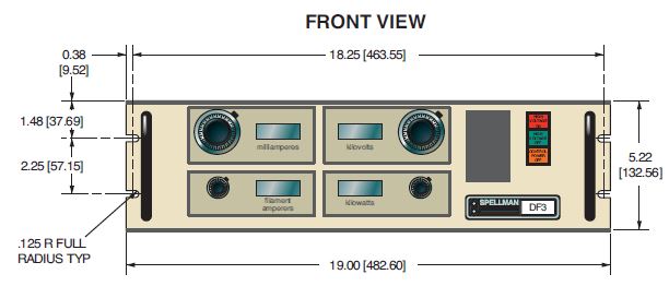
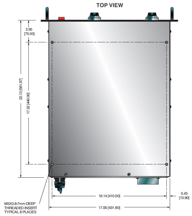
51/4”(3U) H x 19“ W x 22” D (13.3cm x 48.3cm x 55.9cm).
Weight:
90 lbs (40kg).
Regulatory Approvals:
Compliant to EEC EMC Directive. Compliant to EEC Low Voltage Directive.
ADDITIONAL FEATURES
Water Flow Switch:
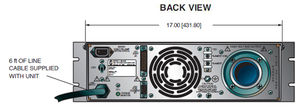
A 24Vdc signal is available on the rear panel to turn on the cooling water to the X-ray tube. This signal can be enabled either when control power is on or when the high voltage is turned on. (Customer must specify).
Fail Safe Interlock:
A 24Vdc signal is available on the rear panel to energize an external X-ray on lamp. This signal is energized when the high voltage is turned on. High voltage will not enable if this circuit is open. (A 220Vac signal is optional).
Preheat and Ramp:
Automatic preheat and ramp control circuits are provided which ramp the kV and mA slowly to set levels. kV ramps in approximately 10 seconds while mA ramps in approximately 20 seconds.
Output Connector:
75kV, 3 conductor Federal Standard X-ray connector. -60kV is connected to terminal “C”. Terminals “S” and “L” are jumped together. The filament output is connected between terminals “C” and “S”. Other configurations are optional. (On the FF3, all output connections S, L, & C are connected together).
Remote Signal Connector:
Remote interface is available via a 50 pin mini D connector. Extensive remote programming and monitoring is provided.
OPTIONS
RS232 - RS232 Interface
220FSI - 220Vac Fail Safe Interlock
208-3P - 208Vac Three Phase Input
Electronic Component (Power Source)
DF/FF series is intended for installation as a component of a system. It is designed to meet CE standards, with conditions of acceptance often being: customer provided enclosure mounting, EMC filtering, and appropriate protection, and isolation devices. The DF/FF series is not intended to be operated by end users as a stand-alone device. The DF/FF series power supply can only be fully assessed when installed within a system, and as a component part within that system.
JB1 MINI D CONNECTOR 50 PIN
| Pin | Signal |
|---|---|
| 1 | +5Vdc (or connect to pin-11) |
| 2 | Control Power On |
| 3 | Intlk |
| 4 | X-Ray On |
| 5 | X-Ray Off |
| 6 | Spare |
| 7 | Spare |
| 8 | Reset |
| 9 | Rmt/Lcl |
| 10 | 24V Switched |
| 11 | +5Vcch |
| 12 | X-ray On Status |
| 13 | Overvoltage |
| 14 | kV Min |
| 15 | Overpower |
| 16 | Filament Current Limit |
| 17 | mA Current Limit |
| 18 | LCL Status |
| 19 | Power Supply Fault |
| 20 | Gnd |
| 21 | Spare |
| 22 | (DF) Remote X-ray On |
| 23 | (DF) Remote X-ray On Ret |
| 24 | Spare |
| 25 | Gnd |
| 26 | kV Ref |
| 27 | kV Com |
| 28 | mA Ref |
| 29 | mA Com |
| 30 | Spare |
| 31 | Spare |
| 32 | Spare |
| 33 | Pwr. Limit (OL Ref) |
| 34 | Pwr. Limit Com (OL Com) |
| 35 | Filament Current Limit |
| 36 | Filament Current Limit Com |
| 37 | Spare |
| 38 | kV Monitor |
| 39 | mA Monitor |
| 40 | Spare |
| 41 | Spare |
| 42 | kV Ref Mon |
| 43 | mA Ref Mon |
| 44 | Spare |
| 45 | Spare |
| 46 | Filament Monitor |
| 47 | Mon Common |
| 48 | Spare |
| 49 | Gnd |
| 50 | Spare |
Tables & Diagrams
DIMENSIONS: in.[mm]
Cost reduced version for OEM quantities available, contact Sales.
Frequently Asked Questions
Application Notes AN-12 – The Benefit of Using a Current Source to Power X-Ray Tube Filament Circuits
Application Notes AN-14 – The Limits of Front Panel Digital Meters
Application Notes AN-01 – Fundamentals of X-Ray Generator – X-Ray Tube Optimization

