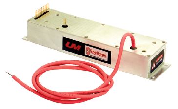
SERIE UM8-40
- 9 rangos de voltaje desde 9KV hasta 40KV, Polaridad Fija negativa o positiva.
- Incrementos de potencia disponibles de salida de 4, 15 y 30 Watts.
- Regulación de Voltaje/Corriente con control de cruce automático.
- Señales de monitor de Voltaje y de Corriente.
- Protegida completamente de arco y corto circuito.
- Salida precisa de +5V de Referencia.
- Interface estandard completa.
- Enlistada CE y cumplimiento RoHS

FUENTES DE ALIMENTACIÓN DE ALTO VOLTAJE DE CD-CD
Diseño de forma, ajuste y función:
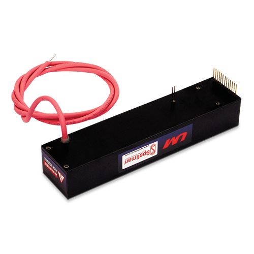
La serie UM de módulos de alto voltaje montables en placa de circuito impreso de Spellman, ofrece al usuario un reemplazo en forma, ajuste y función para las unidades comerciales disponibles actualmente, mientras que proporciona funciones y beneficios adicionales a un precio competitivo. Utilizando la tecnología propia de conversión de energía y la experiencia en alto voltaje de seis décadas de Spellman, estos módulos de alto voltaje basados en tecnología de montaje superficial proporcionan confiabilidad, un funcionamiento superior y una sencilla integración al sistema a un bajo costo en comparación con la competencia.
Topología de conversión de energía avanzada:
Los convertidores UM utilizan una topología propia de conversión de energía por conmutación de voltaje cero, la cual proporciona una eficiencia excepcional además de un bajo nivel de ruido y rizo. Las emisiones irradiadas se reducen en comparación con las topologías de conmutación convencionales, minimizando, o incluso, eliminando la necesidad de blindar la unidad de los circuitos adyacentes.
La salida de alto voltaje se genera utilizando un transformador de elevación de alto voltaje con núcleo de ferrita el cual alimenta un multiplicador de voltaje de media onda Cockcroft-Walton para obtener la salida de alto voltaje especificada.
Gracias a la tasa de conversión de alta frecuencia fija la capacitancia de salida es pequeña, lo que resulta en una acumulación mínima de energía. A través del uso de resistencias limitadoras de sobretensión de clasificación basta y un lazo de corriente de acción rápida, todas las unidades están completamente protegidas contra arco y cortocircuito.
Control y regulación:
El voltaje real de salida generado se muestrea mediante un divisor de alta impedancia para crear una señal de retroalimentación de voltaje. Una señal de retroalimentación de corriente se crea mediante una resistencia sensible a la corriente en el retorno del extremo inferior del circuito de salida de alto voltaje. Estas dos señales precisas de retroalimentación con referencia a tierra se utilizan para regular y controlar con precisión las unidades, además de usarse para propósitos de monitoreo externo.
Gracias a la topología de conversión única de la serie UM, esta puede proporcionar corriente plena a cargas de baja impedancia o incluso a un corto circuito. Las unidades estándar están limitadas al 103% de la corriente de salida máxima nominal.
Interfaz estándar:
La interfaz de la serie UM de Spellman proporciona una función de programación de la corriente, y señales de monitoreo de corriente y voltaje con baja impedancia de salida, amortiguadas y de polaridad positiva (los valores desde cero hasta +4.64 VCD corresponden a los valores desde cero hasta la escala nominal completa). Se suministra una entrada de programación de voltaje donde los valores desde 0 hasta +4.64 VCD corresponden a los valores desde 0 al 100% del voltaje nominal.
El voltaje de baja impedancia amortiguado y las señales de monitoreo de corriente pueden accionar directamente circuitos externos, a la vez que minimizan los efectos de carga y captación de corriente. Estas características ahorran al usuario el gasto y la implementación de un circuito externo de interfaz de amortiguación a la vez que mejoran la integridad general de la señal.
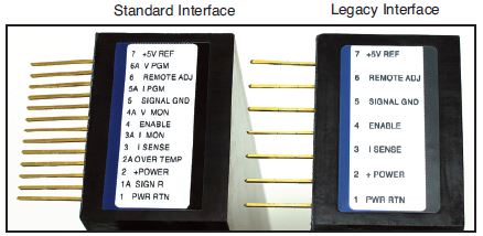
Esta interfaz estándar está disponible mediante una fila de 13 terminales con 0.1 de espacio entre ellas. Se puede proporcionar solicitando la opción "L", una interfaz legada (de 7 terminales con espacio de 0.2 entre ellas) que es compatible con las unidades comercialmente disponibles y actuales.
alConsideraciones mecánicas y ambientales:
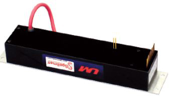
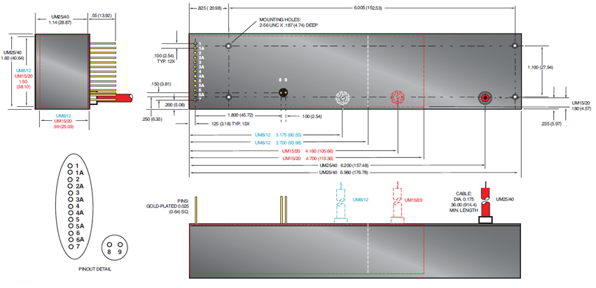
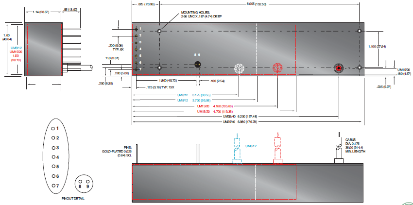
La serie UM son convertidores montables en placa de circuito impreso sólidos y encapsulados dentro de una caja plástica. Todas las unidades están encapsuladas utilizando un material de relleno con base de silicón el cual es considerablemente más ligero en peso que un epóxico. Los tornillos 2-56 aislados sin conexión a tierra se atornillan en dentro del módulo para montar de forma segura la placa de circuito impreso, liberando de cualquier esfuerzo las terminales de la interfaz. También están disponibles como opción placas, soportes y monturas de pestaña para montaje. La salida de alto voltaje se suministra a través de un cable de alto voltaje de 36.00" (914.4 mm) de longitud mínima y capacidad nominal adecuada.
Aprobaciones normativas:
Cumplimiento la Directriz de EMC 2004/108/EC, y la Directriz de Bajo Voltaje 2006/95/EC. Cumple con RoHS. Reconocimiento UL/CUL, Archivo E227588.
Especificaciones
(Rev. 128074-001 REV. P)
Input Voltage:
12Vdc for 4W, 24Vdc for 15W and 30W
Nominal Voltage Range:
11Vdc to 30Vdc for 4W, 23Vdc to 30Vdc for 15W and 30W 4W units can operate at 24Vdc input with no deratings or damage to unit
Input Current: (typical)
Disabled: 10mA @ 24Vdc
Full output, no load: 160mA @ 24Vdc, 300mA @ 12Vdc
Full output, full load:
4 watt units: 330mA @ 24Vdc, 640mA @ 12Vdc
15 watt units: 850mA @ 24Vdc
30 watt units: 1590mA @ 24Vdc
Voltage Regulation:
Line: <0.01% Load: <0.01%
Current Regulation:
Line: <0.01% Load: <0.01%
Stability:
0.01% per 8 hours, 0.02% per day after 30 min. warmup
Accuracy:
2% on all programming and monitoring, except I Sense 10%
Temperature Coefficient: (typical)
Standard: 100ppm/°C
Optional: 25ppm/°C (T Option)
Environmental:
Temperature Range:
Operating: -40°C to 65°C case temperature
Storage: -55°C to 105°C, non operational
Humidity: 10% to 90%, non-condensing.
Cooling:
Convection cooled, typical. 30 watt units operating at full power might require additional cooling to maintain case temperature below 65°C. Methods may include: forced air cooling, use of heat sink or metal case, etc. It is the user’s responsibility to maintain the case temperature below 65°C. Damage to the power supply due to inadequate cooling is considered misuse and repairs will not be covered under warranty.
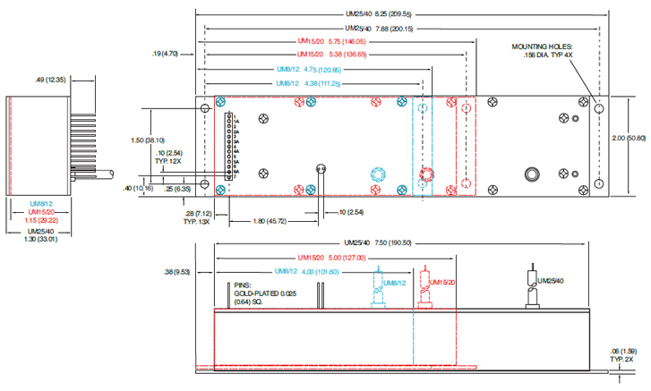
Dimensions:
8kV-12kV: 3.700. L X 1.500. W X 0.990. H (93.98mm X 38.10mm X 25.03mm)
15kV-20kV: 4.700. L X 1.500. W X 0.990. H (119.38mm X 38.10mm X 25.03mm)
25kV-40kV: 6.960. L X 1.600. W X 1.14. H (176.78mm X 40.84mm X 28.87mm)
Weight:
8kV-12kV: 5.7 ounces (162 grams), typical
15kV-20kV: 7.2 ounces (204 grams), typical
25kV-40kV: 13.1 ounces (371 grams), typical
Output Cable:
UM8, UM10, UM12, UM15: TV20 (min. length, 36. (914.4mm)
UM20, UM25: TV30 (min. length, 36. (914.4mm)
UM30, UM35, UM40: TV40 (min. length, 36. (914.4mm)
See product PDF for more specification and features.
UM 4W, 8kV TO 40kV SELECTION TABLE
| Model Number | Output V | Output Current | Ripple(max) %Vp-p | Output Capacitance | Arc Limiting Resistance | I Sense Scaling Full Scale Signal | High Voltage Divider Resistance |
|---|---|---|---|---|---|---|---|
| UM8*4 | 0 to 8kV | 0.5mA | 0.05 | 6830pF | 50kΩ | 5V | 200MΩ |
| UM10*4 | 0 to10kV | 0.4mA | 0.05 | 4380pF | 50kΩ | 2.4V | 300MΩ |
| UM12*4 | 0 to 12kV | 0.333mA | 0.05 | 4380pF | 50kΩ | 3.33V | 300MΩ |
| UM15*4 | 0 to 15kV | 0.266mA | 0.05 | 3220pF | 100kΩ | 1.69V | 400MΩ |
| UM20*4 | 0 to 20kV | 0.2mA | 0.05 | 2310pF | 100kΩ | 1.316V | 550MΩ |
| UM25*4 | 0 to 25kV | 0.16mA | 0.05 | 1540pF | 100kΩ | 1.1V | 800MΩ |
| UM30*4 | 0 to 30kV | 0.133mA | 0.05 | 1370pF | 120kΩ | 0.95V | 900MΩ |
| UM35*4 | 0 to 35kV | 0.115mA | 0.05 | 1370pF | 140kΩ | 0.72V | 900MΩ |
| UM40*4 | 0 to 40kV | 0.1mA | 0.05 | 1370pF | 140kΩ | 1.3V | 900MΩ |
UM 15W, 8kV TO 40kV SELECTION TABLE
| Model Number | Output V | Output Current | Ripple(max) %Vp-p | Output Capacitance | Arc Limiting Resistance | I Sense Scaling Full Scale Signal | High Voltage Divider Resistance |
|---|---|---|---|---|---|---|---|
| UM8*15 | 0 to 8kV | 1.875mA | 0.05 | 6830pF | 50kΩ | 3.75V | 200MΩ |
| UM10*15 | 0 to 10kV | 1.5mA | 0.05 | 4380pF | 50kΩ | 8.152V | 300MΩ |
| UM12*15 | 0 to 12kV | 1.25mA | 0.05 | 4380pF | 50kΩ | 5V | 300MΩ |
| UM15*15 | 0 to 15kV | 1mA | 0.05 | 3220pF | 100kΩ | 5.53V | 400MΩ |
| UM20*15 | 0 to 20kV | 0.75mA | 0.05 | 2310pF | 100kΩ | 4.21V | 550MΩ |
| UM25*15 | 0 to 25kV | 0.6mA | 0.05 | 1540pF | 100kΩ | 3.42V | 800MΩ |
| UM30*15 | 0 to 30kV | 0.5mA | 0.05 | 1370pF | 120kΩ | 2.89V | 900MΩ |
| UM35*15 | 0 to 35kV | 0.429mA | 0.05 | 1370pF | 140kΩ | 2.39V | 900MΩ |
| UM40*15 | 0 to 40kV | 0.375mA | 0.05 | 1370pF | 140kΩ | 4.21V | 900MΩ |
UM 30W, 8kV TO 40kV SELECTION TABLE
| Model Number | Output V | Output Current | Ripple(max) %Vp-p | Output Capacitance | Arc Limiting Resistance | I Sense Scaling Full Scale Signal | High Voltage Divider Resistance |
|---|---|---|---|---|---|---|---|
| UM8*30 | 0 to 8kV | 3.75mA | 0.05 | 6830pF | 50kΩ | 5.36V | 200MΩ |
| UM10*30 | 0 to 10kV | 3mA | 0.05 | 4380pF | 50kΩ | 7.87V | 300MΩ |
| UM12*30 | 0 to 12kV | 2.5mA | 0.05 | 4380pF | 50kΩ | 5V | 300MΩ |
| UM15*30 | 0 to 15kV | 2mA | 0.05 | 3220pF | 100kΩ | 5.29V | 400MΩ |
| UM20*30 | 0 to 20kV | 1.5mA | 0.05 | 2310pF | 100kΩ | 8.15V | 550MΩ |
| UM25*30 | 0 to 25kV | 1.2mA | 0.05 | 1540pF | 100kΩ | 6.56V | 800MΩ |
| UM30*30 | 0 to 30kV | 1mA | 0.05 | 1370pF | 120kΩ | 5.52V | 900MΩ |
| UM35*30 | 0 to 35kV | 0.857mA | 0.05 | 1370pF | 140kΩ | 4.66V | 900MΩ |
| UM40*30 | 0 to 40kV | 0.75mA | 0.05 | 1370pF | 140kΩ | 8.15V | 900MΩ |
STANDARD INTERFACE
| Pin | Signal | Parameters |
|---|---|---|
| 1 | Power Ground Return | +12Vdc or +24Vdc power return/HV return |
| 1A | Signature Resistor | Unique Identifying resistor connected to ground |
| 2 | + Power Input | +12Vdc or +24Vdc power input |
| 2A | OT Output | +5Vdc @ 1mA = Over Temp fault |
| 3 | I Sense | See I Sense text and tables for details |
| 3A | I Mon | 0 to 4.64Vdc = 0 to 100% rated output. Zout < 10kΩ |
| 4 | Enable Input | Low (<0.7V, Isink@1mA)=HV OFF, High (open or >2V)=HV ON |
| 4A | V Mon | 0 to 4.64Vdc = 0 to 100% rated output. Zout < 10kΩ |
| 5 | Signal Ground | Signal Ground |
| 5A | I Pgm | 0 to 4.64Vdc = 0 to 100% rated output. Zin > 47kΩ Leave open for preset current limit @103% of rated output current |
| 6 | Remote Adjust | Positive Polarity Unit: 0 to +4.64VDC = 0 to 100% rated voltage, Zin >1MΩ Negative Polarity Unit: +5VDC to 0.36V = 0 to 100% rated voltage, Zin >100kΩ Leave open if pin 6A (VPgm) is used for programming |
| 6A | V Pgm | 0 to 4.64Vdc = 0 to 100% rated voltage. Zin > 100kΩ Leave open if pin 6 (remote adjust) is used for programming |
| 7 | +5V Reference Output | +5Vdc ±1%, 25ppm/°C. Zout =475Ω |
| 8 | HV Ground Return | HV Ground Return |
| 9 | E Out Monitor | 1000:1 ratio. Polarity of Voltage Monitor signal equals polarity of unit. Accuracy is ±2%, 100ppm/°C. Calibrated with DVM with 10MΩ input impedance |
Grayed out signals are provided for backward legacy compatibility and their use is not required.
Power Ground Return, Signal Ground and HV Ground Return are connected internally. For best performance they should not be connected externally.
LEGACY INTERFACE (L OPTION)
| Pin | Signal | Parameters |
|---|---|---|
| 1 | Power Ground Return | +12Vdc or +24Vdc power return/HV return |
| 2 | + Power Input | +12Vdc or +24Vdc power input |
| 3 | I Sense | See I Sense text and tables for details |
| 4 | Enable Input | Low (<0.7V, Isink@1mA)=HV OFF, High (open or >2V)=HV ON |
| 5 | Signal Ground | Signal Ground |
| 6 | Remote Adjust | Positive Polarity Unit: 0 to +4.64VDC = 0 to 100% rated voltage, Zin >1MΩ Negative Polarity Unit: +5VDC to 0.36V = 0 to 100% rated voltage, Zin >100kΩ |
| 7 | +5V Reference Output | +5Vdc ±1%, 25ppm/°C. Zout =475Ω |
| 8 | HV Ground Return | HV Ground Return |
| 9 | E Out Monitor | 1000:1 ratio. Polarity of Voltage Monitor signal equals polarity of unit. Accuracy is ±2%, 100ppm/°C. Calibrated with DVM with 10MΩ input impedance |
Power Ground Return, Signal Ground and HV Ground Return are connected internally. For best performance they should not be connected externally.
Standard Interface Connections
Fifteen (15) gold plated 0.025˝ (0.64mm) square pins suitable for direct PCB mounting.
Legacy Interface Connections
Nine (9) gold plated 0.025˝ (0.64mm) square pins suitable for direct PCB mounting.
See mechanical drawing for location and spacing details
Programming and Monitor Signals
Voltage and current programming is done via positive polarity, high input impedance, 0 to 4.64Vdc signals.
Voltage and current monitors are positive polarity, buffered low output impedance 0 to 4.64Vdc signals.
I Mon
The I Mon signal is a true output current monitoring signal. All internal offsets due to feedback divider currents have been compensated for.
Signature Resistor
A unique identifying signature resistor for each type of unit is connected from Pin 1A to ground. Details if desired are available upon request.
I Sense Signal
The polarity of the I Sense signal is opposite of the polarity of the output voltage of the unit that generated it. So a positive output polarity unit creates a negative polarity current monitor signal; while a negative output polarity unit creates a positive polarity current monitoring signal. This signal is clamped to ground internally via a bidirectional transient protection device and the signal is made available via a series connected 47kΩ isolation resistor. Internal HV dividers create a small,
linear offset voltage on this current monitor signal that can be compensated for.
OT Output
The unit is protected by an internal thermostat that will shut the unit off if the case temperature exceeds 65°C. The OT Output signal will change states indicating an over temperature fault has occurred. In order to clear the OT signal and re-enable the unit, the temperature has to drop below 55 degrees C and input power needs to be recycled. For details on unit cooling requirements and the OT Output signal please see the operator’s manual.
Tablas y Diagramas
UM8-40 OPTIONS
T Option
Low Temperature Coefficient-
The T Option offers the UM with an improved temperature coefficient. The standard voltage feedback divider is replaced with one having a superior temperature coefficient, resulting in a unit with 25ppm/C° (typical) temperature coefficient.
PHYSICAL INTERFACING
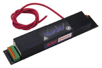
B Option
Terminal Block-
The B Option provides terminal block connections for both the customer interface and high voltage output/return.
This feature can be helpful in situations where frequent wiring changes are anticipated, as in a testing or prototype environment.
SHIELDING OPTIONS
S Option
RF Tight Shielded Can-
The S Option mounts the UM module inside of a flanged RF tight aluminum can.
SHIELDING OPTIONS (CONT)
M Option
Mu Metal Shield-
UM modules can be fitted with an adhesive backed Mu Metal foil shield to help protect sensitive adjacent circuitry.
Same as standard unit.
CHASSIS MOUNTING OPTION
E Option
Eared Mounting Plate-
An eared mounting plate is affixed to the top surface of the UM module allowing simple chassis mounting of unit.
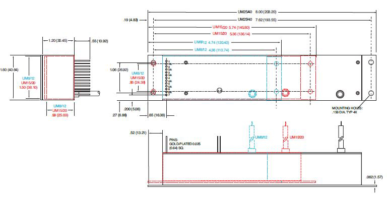
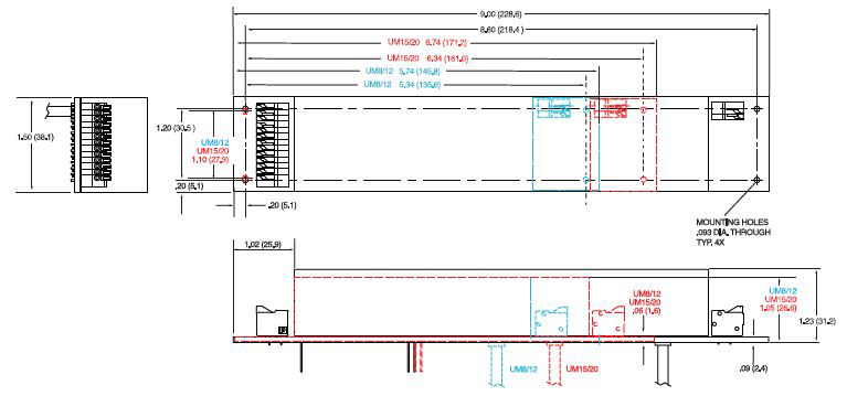
DIMENSIONS: in.[mm]
15 PIN - Standard Interface
9 PIN - Legacy Interface
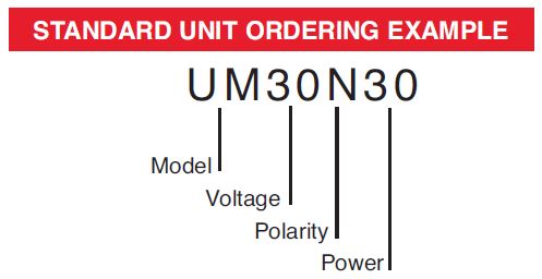
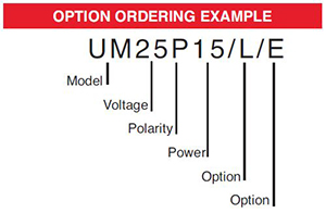
ORDERING INFORMATION
| Voltage | 0 to 8kV | 8 |
| 0 to 10kV | 10 | |
| 0 to 12kV | 12 | |
| 0 to 15kV | 15 | |
| 0 to 20kV | 20 | |
| 0 to 25kV | 25 | |
| 0 to 30kV | 30 | |
| 0 to 35kV | 35 | |
| 0 to 40kV | 40 | |
| Polarity | Positive | P |
| Negative | N | |
| Power | Watts Output | 4 |
| Watts Output | 15 | |
| Watts Output | 30 |
STANDARD UNIT ORDERING EXAMPLE
OPTION ORDERING INFORMATION
| OPTION | OPTION CODE |
|---|---|
|
Legacy Interface |
L |
| Low Temperature Coefficient | T |
| Mu Metal Shield | M |
| RF Tight Shielded Can | S |
| Eared Mounting Plate | E |
| Terminal Block | B |
Frequently Asked Questions
What Is a Safe Level of High Voltage?
Where Can I Obtain Information on High Voltage Safety Practices?
What Kind of High Voltage Connector Do You Use on Your Supplies?
What Do You Mean That the Output Side of the High Voltage Cable on Most Standard Products Is “Unterminated”?
How Should I Ground Your Supply?
Why Is Arcing an Issue for a High Voltage Power Supply?

