SERIE DXM
- Modelos de 20 kV-160 kV, 300 W, 600 W y 1200 W
- Entrada universal, factor de potencia corregido
- Capacidad de tubo de rayos X de ánodo y cátodo caliente
- Interfaces estándar USB, Ethernet y RS-232
- Cumplimiento CE, reconocimiento UL, cumple con RoHS
- Rampa y deteccion de arco programables por el usuario
*Nota: Todas las especificaciones están sujetas a cambios sin previo aviso. Consulte la versión en PDF en inglés de esta hoja de datos para obtener la revisión más actualizada.
![]()
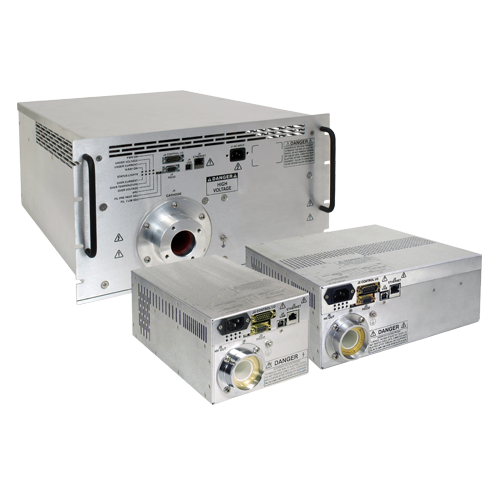
GENERADORES DE RAYOS X INDUSTRIALES DE 300 W-1200 W
Los nuevos módulos generadores de rayos X de la serie DXM de Spellman están diseñados para aplicaciones de OEM de hasta 75 kV a 1200 W. Su entrada universal, tamaño de paquete pequeño y la elección de las tres interfaces estándar simplifica la integración de la DXM en su sistema de análisis de rayos X. Los modelos están disponibles para operar diseños de tubos de rayos X de filamento flotante (polaridad de alto voltaje negativa) o filamentos con referencia a tierra (polaridad de alto voltaje positiva). El circuito de control de emisión basado en un procesador de señal digital (DSP) proporciona una regulación excelente de la corriente de emisión y una sobresaliente estabilidad y desempeño.
Aplicaciones típicas:
- Clasificación de plásticos
- Inspección de cristales
- Medición de revestimientos
- Inspección de diamantes
- Análisis de minerales
- Fluorescencia de rayos X
- Difracción de rayos X
![]()
Especificaciones
(Ref. 128034-001 REV. AG)
Input Voltage:
Power factor corrected input
100-240Vac ±10% (90-264Vac):
47-63Hz @ 4.6A for 300 watt units
200-240Vac ±10% (180-264Vac):
47-63Hz @ 4.3A for 600 watt units
47-63Hz @ 8.2A for 1200 watt units
Output Voltage:
7 models—20kV, 30kV, 40kV, 50kV, 60kV, 70kV, 75kV and 160kV
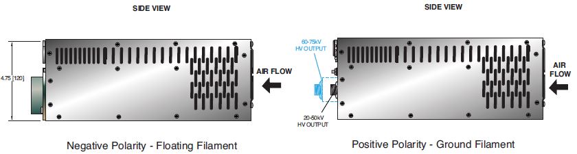
Output Polarity:
Negative-for floating filament X-ray tubes
Positive-for ground referenced filament X-ray tubes
Power:
3 power ranges available—300 watts, 600 watts and 1200 watts
Other power levels available on special order.
Output Voltage Regulation:
≤ 0.01% of rated output voltage over specified input voltage range
≤ 0.01% of rated output voltage for a full load change
Emission Current Regulation:
≤ 0.01% of rated output current over specified input voltage range
≤ 0.01% of rated output current for a change from 30% to 100% of rated output voltage
Filament is disabled when kV is <30% of full scale output
Ripple:
≤ 1%rms at >20 kHz, 0.1%rms below 20 kHz
Stability:
≤ 25ppm/hr after a 2 hour warm up
Temperature Coefficient:
≤ 50ppm per degree C
Environmental:
Temperature Range:
Operating: 0°C to 40°C
Storage: -40°C to 85°C
Humidity:
20% to 85% RH, non-condensing.
Filament Configuration:
Closed loop emission control regulates filament setting to provide desired X-Ray tube emission current. Two types are available: Floating Filament (ac output referenced to negative output voltage) and Ground Referenced Filament (dc output referenced to ground).
Output:
0-5 amps at a compliance of 10 volts, maximum. The filament loop is disabled when the kV output is less than 30% of full scale output to protect the X-Ray tube. Other filament levels available on special order.
Control Interface
Local Interface:
Potentiometers are provided to adjust filament limit and preheat levels
Remote Interface:
USB, Ethernet and RS232 are standard. All digital monitors have an accuracy specification of 2%
Control Software:
A Windows graphical user interface example is provided.
High Voltage Enable:
A hardware based, dry contact closure will enable the power supply into the high voltage on mode
Monitor Signals:
Voltage and current monitor signals are scaled 0-10Vdc equals 0-100% of full scale, accuracy is 1%
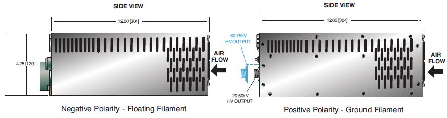
Cooling:
Forced air
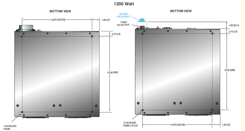
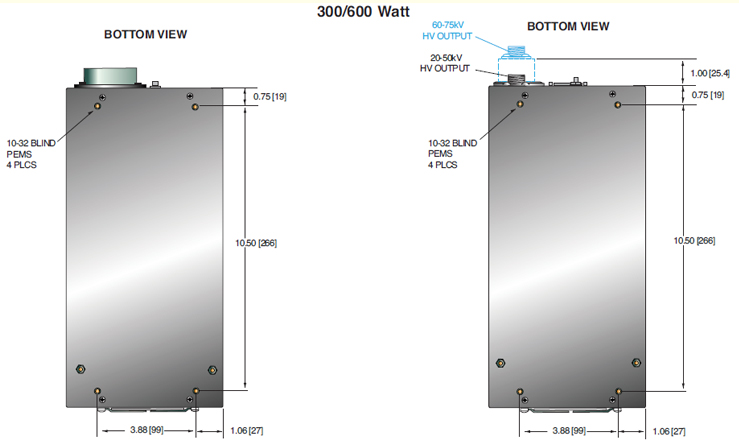
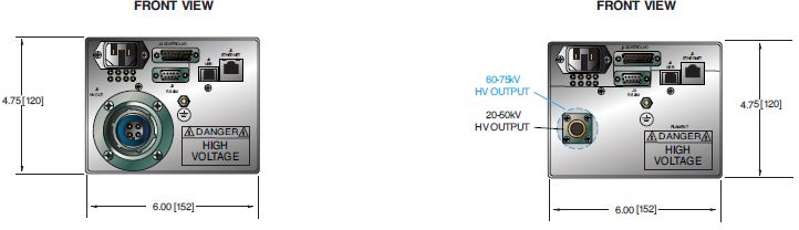
Dimensions:
300/600 Watts: 4.75. H X 6. W X 12. D
(120.65mm x 152.4mm x 304.8mm)
1200 Watts: 4.75. H X 12. W X 12. D
(120.65mm x 304.8mm x 304.8mm)
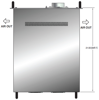
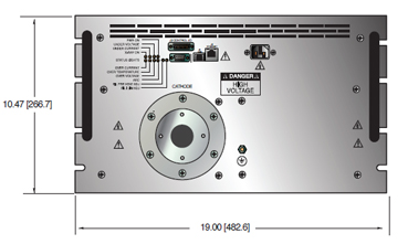
160kV: 10.5˝ H X 19˝ W X 21.5˝ D
(266.7mm x 482.6mm x 546.1mm)
Weight:
300/600 Watts: 14 pounds (6.35kg)
1200 Watts: 26 pounds (11.8kg)
160kV: 142 pounds (66.4kg)
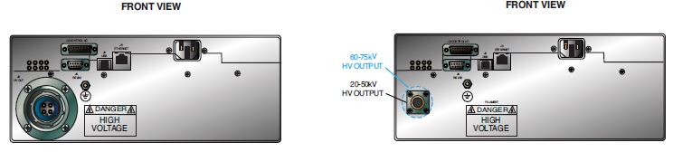
Input Line Connector:
IEC320 with EMI filter
Output Connector:
Depends upon polarity selected. See table and drawing.
Other connectors and pinouts available on special order.
Regulatory Approvals:
Compliant to EEC EMC Directive. Compliant to EEC Low Voltage Directive. UL/CUL recognized, File E227588. RoHS Compliant.
DXM SELECTION TABLE— 300W, 600W, 1200W
| 300 Watt | 600 Watt | 1200 Watt | ||||
|---|---|---|---|---|---|---|
| kV | mA | Model | mA | Model | mA | Model |
| 20 | 15 | DXM20*300 | 30 | DXM20*600 | 60 | DXM20*1200 |
| 30 | 10 | DXM30*300 | 20 | DXM30*600 | 40 | DXM30*1200 |
| 40 | 7.5 | DXM40*300 | 15 | DXM40*600 | 30 | DXM40*1200 |
| 50 | 6 | DXM50*300 | 12 | DXM50*600 | 24 | DXM50*1200 |
| 60 | 5 | DXM60*300 | 10 | DXM60*600 | 20 | DXM60*1200 |
| 70 | 4.28 | DXM70*300 | 8.56 | DXM70*600 | 17.12 | DXM70*1200 |
| 75 | 4 | DXM75*300 | 8 | DXM75*600 | 16 | DXM75*1200 |
| 160 | 7.5 | DXM160N1200 | ||||
*Specify “P” for positive polarity or “N” for negative polarity
FILAMENT TERMINAL BLOCK— TB1 TWO POSITION TERMINAL BLOCK
| Pin | Signal | Signal Parameters |
|---|---|---|
| 1 | Filament Output | 0-5 amps, 10Vdc Maximum |
| 2 | Filament Output | Filament Return |
For positive polarity/ground referenced filament units
DXM ANALOG INTERFACE— J2 15 PIN MALE D CONNECTOR
| Pin | Signal | Signal Parameters |
|---|---|---|
| 1 | Power Supply Fault | Open Collector, 35V @ 10mA Maximum |
| 2 | Current Program In | 0 to 10V=0 to 100% Rated Output, Zin=10MΩ |
| 3 | Voltage Program In | 0 to 10V=0 to 100% Rated Output, Zin=10MΩ |
| 4 | Filament Limit Input | 0 to 10V=0 to 100% Rated Output, Zin=10MΩ |
| 5 | Local Filament Limit | Multi-turn front panel potentiometer |
| 6 | Filament Preheat Input | 0 to 10V=0 to 100% Rated Output, Zin=10MΩ |
| 7 | Local Filament Preheat | Multi-turn front panel potentiometer |
| 8 | Voltage Monitor | 0 to 10V=0 to 100% Rated Output, Zout =4.99k, 1% |
| 9 | Signal Ground | Ground |
| 10 | Current Monitor | 0 to 10V=0 to 100% Rated Output, Zout =4.99k, 1% |
| 11 | X-ray Enable Input | Connect to Pin 12 to HV Enable Supply |
| 12 | X-ray Enable Output | +15V @ Open, ≤15mA @ Closed |
| 13 | Filament Monitor | 1 Volt=1 Amp, Zout=10kΩ |
| 14 | X-ray On Output Signal | Open Collector, 35V @10mA Maximum |
| 15 | Spare | N/C |
RS-232 DIGITAL INTERFACE— J3 9 PIN FEMALE D CONNECTOR
| Pin | Signal | Signal Parameters |
|---|---|---|
| 1 | N/C | No Connection |
| 2 | TX out | Transmit Data |
| 3 | RX in | Receive Data |
| 4 | N/C | No Connection |
| 5 | SGND | Ground |
| 6 | N/C | No Connection |
| 7 | N/C | No Connection |
| 8 | N/C | No Connection |
| 9 | N/C | No Connection |
USB DIGITAL INTERFACE— J4 4 PIN USB "B" CONNECTOR
| Pin | Signal | Signal Parameters |
|---|---|---|
| 1 | VBUS | +5 Vdc |
| 2 | D- | Data - |
| 3 | D+ | Data + |
| 4 | GND | Ground |
ETHERNET DIGITAL INTERFACE— J5 8 PIN RJ45 CONNECTOR
| Pin | Signal | Signal Parameters |
|---|---|---|
| 1 | TX+ | Transmit Data + |
| 2 | TX- | Transmit Data 3 |
| 3 | RX+ | Receive Data + |
| 4 | N/C | No Connection |
| 5 | N/C | No Connection |
| 6 | RX- | Receive Data - |
| 7 | N/C | No Connection |
| 8 | N/C | No Connection |
R24 HV CONNECTOR PINOUT J6 CATHODE OUTPUT (160kV)
| Pin | Output Connection |
|---|---|
| C (common) | High Voltage Output |
| S (small) | High Voltage Output |
| L (large) | Filament Output |
HIGH VOLTAGE OUTPUT CONNECTOR—
J6 FLOATING FILAMENT
20kV-75kV Negative Polarity:
Claymount Mini Federal standard X-Ray connector
160kV Negative Polarity:
R24 (cable not provided)
HIGH VOLTAGE OUTPUT CONNECTOR—
J6:GROUND FILAMENT
Positive Polarity: Spellman High Voltage
Delrin Drywell connector.
4 foot (1.21m) long high voltage cable provided
For positive polarity units a ground referenced filament output is provided on a two position terminal TB1. See table
CLAYMOUNT HV CONNECTOR
| Pin | Output Connection |
|---|---|
| C (common) | High Voltage Output |
| S (small) | High Voltage Output |
| L (large) | Filament Output |
| G (grid) | Filament Output |
Note: No high voltage cable is provided
Recommended Cable: Claymount part number: 12096
Cable assembly, L3 CA11, CA11, 10F, CS=Bare 10 foot, Mini Federal Connectors on both ends, "C" and "S" are both connected to the bare shield wire
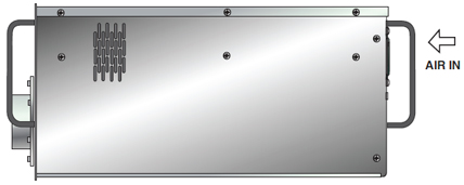
Tablas y Diagramas
DIMENSIONS: in.[mm]
160kV
TOP VIEW
FRONT VIEW
SIDE VIEW
DIMENSIONS: in.[mm]
Frequently Asked Questions
Application Notes AN-12 – The Benefit of Using a Current Source to Power X-Ray Tube Filament Circuits
Application Notes AN-01 – Fundamentals of X-Ray Generator – X-Ray Tube Optimization

