
Application Notes - X-Ray Generators
Fundamentals of X-RAY Generator – X-Ray Tube Optimization:
AN-01
X-Ray generators and X-Ray tubes work together to provide performance and reliability demanded in today’s applications. Spellman X-Ray generators offer customers sophistication and flexibility to customize how the generator operates tubes provided by all manufacturers in order to meet the specific goals of your project. To harness the full potential of Spellman X-Ray generators it’s important to understand a few fundamental rules when setting up your generator in order to optimize performance and reliability.
If you have a specific question just ask the experts at: asktheexperts@spellmanhv.com
Understanding how to match the settings of the X-Ray generator to the X-Ray tube.
- Confirm Specifications: Before ordering your high voltage generator/ X-Ray tube/high voltage cable confirm the filament current and voltage, output kV and mA specifications of the generator meet the requirements of the X-Ray tube. Additionally check the high voltage cable pinout and length are per the Spellman High Voltage product specifications.
- Set Max Filament Limit: One of the most critical settings is the Filament Limit adjustment. The Filament Limit set point limits that maximum output current of the filament power supply to protect the filament of the X-Ray tube. This setting will make it impossible for the generator to exceed this value in any circumstance. It should be set at or below the X-Ray tube manufacturer’s specification. When setting it below the maximum X-Ray tube specification, the Filament Limit should be 10-15% higher than the filament current required to achieve the maximum programmed emission current (mA) at the lowest kV. Remember, filament maximum values are different than the REQUIRED values for emission. Setting 10-15% over the needed emission current values provides headroom as well as better transient response. But always keep the limit level at or below the manufacturer's recommended maximum filament current specification. See the user’s manual for more details.
- Set Filament Standby (Preheat): The Filament Standby current (referred to as Filament Preheat on some product lines) is the idle current supplied to the X-Ray tube filament during X-Ray Standby (HV OFF/X-Ray disabled) conditions. The Filament Preheat set point is typically around 1A - 2A, but the X-Ray tube manufacturer should be consulted. It is perfectly fine to set standby current to zero, if fast emission ramping is not required.
- Program Ramp Times: If programmable kV, mA and filament ramp times are available for the product you are using, these should be set to the slowest time tolerable for your applications. Refer to specific product manuals for these features or consult with Spellman High Voltage.
Effects of cable length on filaments:
AC filaments:
AC filaments operate at high frequency so there is a potential difficulty driving power down the long cable due to its impedance. Standard units are calibrated with a defined cable length (for example the DXM is 3 meters) during factory testing. Changing the high voltage cable length may have an effect on the filament current calibration. If you have a concern about the cable length in your system, contact Spellman High Voltage.
DC filaments:
For DC filaments the DC copper losses of the cable need to be considered. The wire gauge used should be sized for the current requirement. Standard units are calibrated with a defined cable length and wire gauge (for example the DXM is a 3 meter, 18 gauge wire).
Filament voltage requirements:
Spellman uses current regulation for filament control. The voltage needed by the X-Ray tube filament is simply a result of Ohms law: V=I*R. If you are not sure what the current and voltage requirements of your X-Ray tube are, consult the X-Ray tube manufacturer or Spellman High Voltage.
mA loop response and how we design X-Ray generators to operate with a majority of X-Ray tubes.
Not all X-Ray tubes have the same filament characteristics. Different filament characteristics require a different control response to provide stable emission current output. Our standard units have an emission control response designed to work with many X-Ray tubes. Some X-Ray tubes fall outside of this category and require custom emission loop compensation to insure stable emission output. Consult Spellman High Voltage about your specific X-Ray tube being used.
An explanation of our KV, mA and filament ramp speeds and why?
Spellman standard products are designed to be used with a wide variety of X-Ray tubes and applications. Because some applications require faster rise times (less than 2 seconds) and other applications prefer slower rise times, the standard product ramps are defaulted to speeds that will meet most requirements and applications. For example, the DXM has a default 5 second kV ramp and a 2.5 second filament ramp, but can be adjusted. Please consult with the X-Ray tube manufacturer about ramp time specification requirements for the specific X-Ray tube to be used.
Of course we can customize and slow down the ramps, but why not make the standard product ramps as slow as possible?
Some applications require faster rise times (less than 2 seconds) and other applications prefer slower rise times. The standard product ramps are defaulted to speeds that will meet most requirements and applications. Please consult with Spellman High Voltage about customizing ramps speeds to meet your application.
Slower kV ramp times can be better for the X-Ray tubes, allowing a controlled voltage distribution along the tube. Slower Filament and mA ramps can minimize stress on the X-Ray tube filament. Consult with the X-Ray tube manufacturer for recommended ramping for your X-Ray tube.
Remember an X-Ray tube is a limited lifetime device. It degrades over time as the filament evaporates. The higher the current the faster the evaporation and the shorter the life of the tube. The slower voltage and current changes are applied to the filament the less stress and longer the life.
Example of faster ramp times:
Filament Limit Set Point 3.6A
Preheat Set Point 0.0A
CH1 (YELLOW) mA Tube Current Monitor
CH2 (GREEN) kV Monitor (1 second ramp time)
CH3 (PURPLE) Filament Current Monitor (750ms ramp time to 3.6A filament limit)
CH4 (BLUE) mA Program Ramp (1 second ramp time after a 1 second hold period at 5% of mA program value)
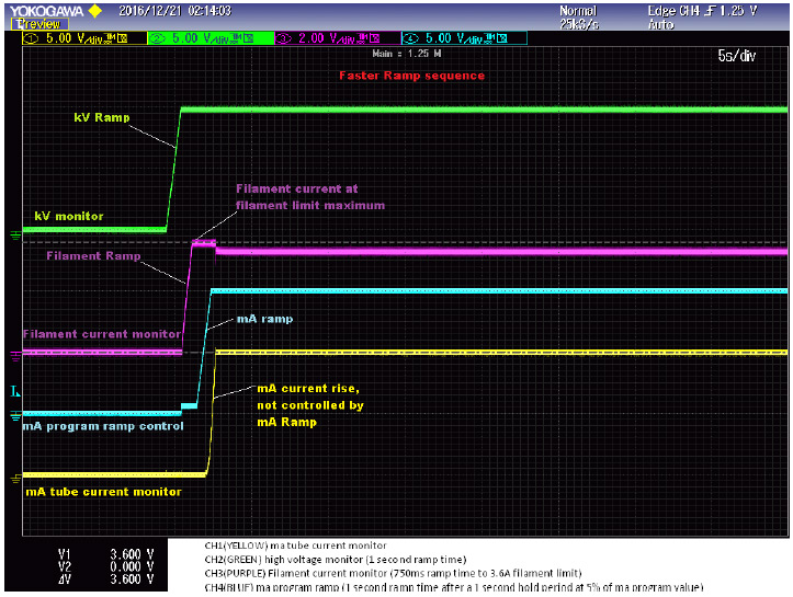
As you can see in the waveform above the faster ramp sequence does not allow enough time for the X-Ray tube filament to achieve the required temperature for emission current before the mA ramp starts. The causes the filament current to ramp to the maximum filament limit and stay at that level for several seconds while the filament reaches required temperature for the requested emission current. The mA current rise is not controlled by the mA ramp and hence may have a slight over shoot.
Example of slower ramp times:
Filament Limit Set Point 3.6A
Preheat Set Point 0.0A
CH1 (YELLOW) mA Tube Current Monitor
CH2 (GREEN) kV Monitor (10 second ramp time)
CH3 (PURPLE) Filament Current Monitor (22 second ramp time to 3.6A filament limit)
CH4 (BLUE) mA Program Ramp (5 second ramp time after a 30 second hold period at 5% of mA program value)
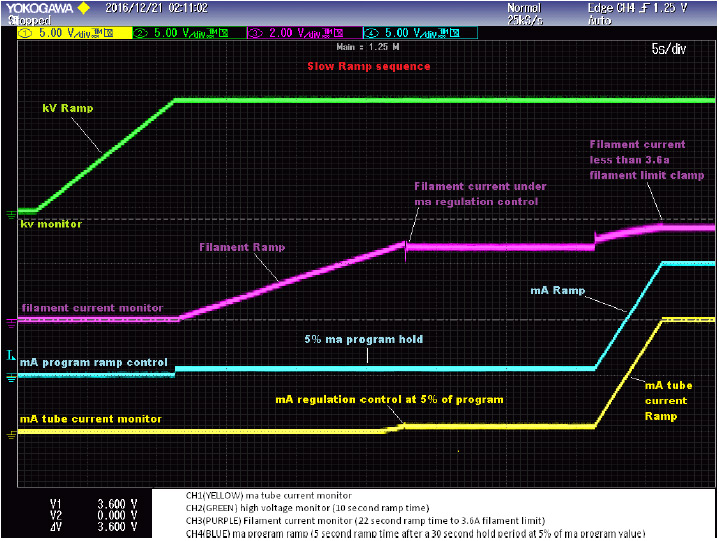
As you can see above in the waveform above, at the completion of the kV ramp the mA program steps to 5% of the programmed mA value. At the same time the filament slowly ramps up allowing mA regulation to take control. After mA regulation is in control and stabilizes, the mA ramps to the final program value with no over shoot. Note the filament current never goes to the maximum filament limit set point of 3.6A.

