
PDM90PN900 Series Monoblock® X-Ray Generators
- X-Ray Source with Integrated Filament, Tube and Beam Port
- Separate Control Electronics Box
- Compact & Lightweight
- Analog or Digital Control Interface
*Note: All specifications are subject to change without notice. Please consult the English PDF version of this datasheet for the most up-to-date revision.

Panoramic Dental X-Ray Source
Spellman’s new Panoramic Dental Monoblock® consists of an integrated X-Ray tube, dual-output high voltage power supply, and filament supply with control circuitry. The PDM90PN900 is designed for extra oral dental X-Ray applications including CT and Panoramic X-Ray. Features like small package size, standard analog and RS-232 digital interface simplify integrating this Monoblock® into your X-Ray system. Proprietary emission control circuitry provides excellent regulation of X-Ray tube current, along with outstanding stability and performance.
Typical applications:
- Dental X-Ray: Panoramic and CT Imaging
Specifications
(Ref. 128109-001 REV. D)
X-Ray Tube Characteristics:
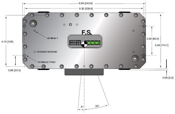
Target Angle: 5 degrees
Focal Spot: 0.5mm nominal
Beam Filtration: 3.0mm of Al equivalent
Beam Geometry: see page 3
X-Ray Tube Voltage:
Nominal X-Ray tube voltage is adjustable between 50kV to 90kV
Voltage Regulation:
Line: ±0.5% for a ±1V change of nominal input line voltage
Load: ±0.1% for a load change of 25µA to maximum rated current
X-Ray Tube Current:
1mA to 10mA over specified tube voltage range
Current Regulation:
Line: ±0.5% for a ±1V change of nominal input line voltage
Load: ±0.5% for a voltage change of 35kV to 80kV
X-Ray Tube Power:
900 watts peak power
Duty Cycle:
CT (Pulsed): ≤ 45 seconds scan time cycle at up to 40 pulses per second available
Panoramic (Continuous): Maximum scan time = 30s, with 60s off-time. Five consecutive scans
Input Voltage:
100-240Vac ±10% 50/60 Hz, 10 amps RMS maximum
Interface:
The RS-232 serial communications interface will be used to program and monitor output voltage and current, control various functions and report status and faults.
Digital Interface Connector:
RS-232: 9 pin D connector, male
Operating Temperature:
0°C to +40°C
Storage Temperature:
-20°C to +70°C
Humidity:
5% to 95% relative humidity, non-condensing
Cooling:
Tank: Convection
Controller: Forced air via provided fan
Dimensions:
X-Ray Tank: 9.7"W X 7.7"H X 4.7"D (247mm X 195mm X 119mm)
Inverter/Controller: 7.10"W X 9.80"H X 3.60"D (180mm X 250mm X 92mm)
Weight:
X-Ray Tank: 17lbs (7.7kg)
Inverter/Controller: 6.5lbs (3kg)
X-Ray Leakage:
Less than 100mR/hour (or <1mGy/hr) @ 1meter from the Monoblock® surface.
Regulatory Approvals:
Compliant to EMC 60601-1-2 (external EMC filter and shielding required). UL/CUL recognized file E242584.
| Pin | Signal | Parameters |
|---|---|---|
| 1 | X-Ray Ready/Sync | +5 V Logic |
| 2 | X-Ray Enable | +5 V Logic |
| 3 | + X-ray Signal (Exgate) | +5VDC = Enable X-Ray, Low (or Open) = Disable X-Ray |
| 4 | Signal Ground | Signal Ground |
| 5 | VMTR Signal (KV monitor) | Voltage: 0 to +5.00 V max, Scale Factor: 0 – 5.00 Vdc = 0 to 100 kV |
| 6 | Signal Ground | Signal Ground |
| 7 | IMTR Signal (mA monitor) | Voltage: 0 to +5.00 V max, Scale Factor: 0 – 5.00 Vdc = 0 – 12.1mA |
| 8 | Fault Signal | Output signal: Open Collector, High (Open) = No Fault |
| 9 | HV ON Lamp, Relay N/O | Relay Normally Open, Dry contacts rated 1A or less will handle a nominal 50mA DC load. |
| 10 | HV ON Lamp, Common | Common |
RS-232 DIGITAL INTERFACE— J5 9 PIN MALE D CONNECTOR
| Pin | Signal | Parameters |
|---|---|---|
| 1 | N/C | No Connection |
| 2 | TX | Transmit Data |
| 3 | RX In | Receive Data |
| 4 | N/C | No Connection |
| 5 | SGND | Signal Ground |
| 6 | N/C | No Connection |
| 7 | N/C | No Connection |
| 8 | N/C | No Connection |
| 9 | N/C | No Connection |
LED INDICATORS
| Indicator | Signal Name | Condition Illuminated When... |
|---|---|---|
| LED 1 | OV | High kV occurs |
| LED 2 | UV | Low kV occurs |
| LED 3 | UC | Low mA occurs |
| LED 4 | OC | High mA occurs |
| LED 5 | ARC FLT | Arc fault occurs |
| LED 6 | OT | Over temperature occurs |
| LED 7 | PW (Pulse mode) | Pulse mode selected |
| LED 8 | CW (CW mode) | CW mode selected |
| LED 9 | CW (CW mode) | X-Ray is ON |
Tables & Diagrams
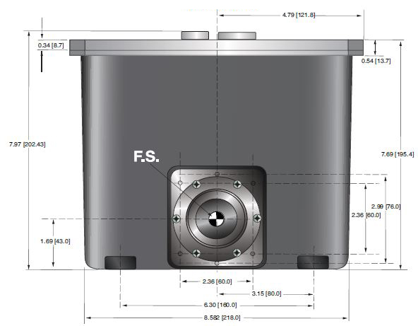
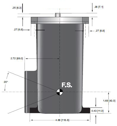
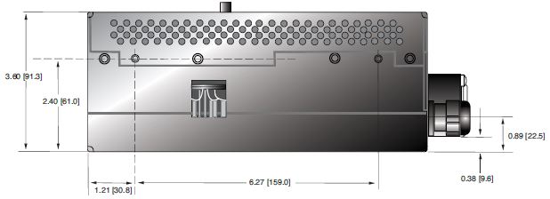
DIMENSIONS: in.[mm]
PDM Generator Tank
TOP VIEW
FRONT VIEW
SIDE VIEW
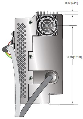
PDM Inverter/Controller
TOP VIEW
FRONT VIEW
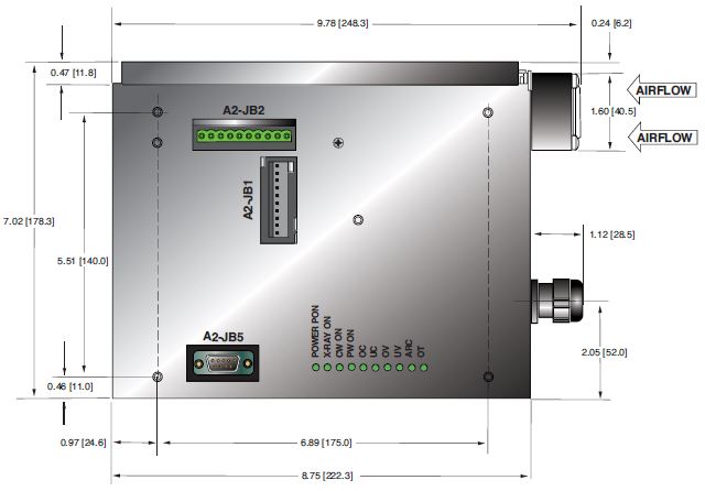
SIDE VIEW
Frequently Asked Questions
Why Is Oil Insulation Used?
Do I Need to Ensure My Monoblock® Stays Cool? Why?
How Often Do I Need to Season My Monoblock® X-Ray Source? Why?
Application Notes AN-12 – The Benefit of Using a Current Source to Power X-Ray Tube Filament Circuits

