")
MX8Plus
- ±8kV 25mS Polarity Reversing Speed
- Optimized for EI and APCI Applications
- Precision Analog Voltage and Current Controls and Monitors
- High Stability
- Low Ripple and Noise
- High Voltage Inhibit Control
- UL Recognized, CE Marked and RoHS Compliant
*Note: All specifications are subject to change without notice. Please consult the English PDF version of this datasheet for the most up-to-date revision.


High Performance High Voltage Power Supply
Spellman's MX8 Plus is a well-regulated high performance fast reversible supply featuring a 25ms "hot switchable" polarity reversing capability.
The MX8 Plus's low ripple specification is typical of the topologies that make Spellman High Voltage your ideal choice for mass spectrometry applications; especially security detection systems, dynodes, sample ionisation as well as capillary electrophoresis and electrostatic printing applications. The MX8 has been designed especially for EI and APCI applications.
The MX8 Plus can be easily tailored to an OEM's requirement, such as improved ripple performance, or different voltage and/or current capabilities.
Typical applications:
- Mass Spectrometry
- Capillary Electrophoresis
- Electrostatic Printing
Specifications
(Ref. 128067-001 REV. J)
SPECIFICATIONS
Input Voltage:
+24Vdc, ±10%
Input Current:
<0.5A nominal continuous
<1.2A peak during reversing
Output Voltage:
0V to ±8kV (Linearity not guaranteed below 200V. Maximum offset ±20V when programmed to zero or disabled using remote enable.)
Output Current:
0 to 100µA max
Output Polarity:
Remotely reversible via TTL logic signal
Polarity Reversal Time:
<25ms from change of polarity command to 90% of output into 100pF load capacitance. (Unit incorporates circuitry to minimize the effects of low programmed current on reversing time. Polarity reversal time applies when current is programmed to 3μA or above.)
Voltage and Current Regulation:
Line: <0.1% for ±10% input voltage change
Load: <0.1% for 0 to full load
Ripple:
<0.1% p-p @ 100μA
Temperature Coefficient:
≤ 100ppm per degree C
Environmental:
Temperature Range:
Operating: 5°C to 45°C
Storage: -35°C to 85°C
Humidity:
10% to 85%, non-condensing
Stability:
<0.05% per hour after 1 hour warm up
Protection:
Arc and short circuit protected
Output Voltage Limit:
Output voltage must not exceed ±8kV ±250V under any input or output conditions
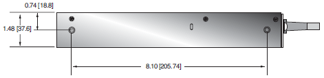
Dimensions:
1.48. H X 3.23. W X 9.45. D (37.6mm X 82mm X 240mm)
Weight:
2.4 pounds (1.1kg)
Input Connector:
14 way Molex receptacle p/n 39-01-2140. Cable length 508mm, mating connector not provided
Output Connector:
Alden F303RX, mating connector not provided
Regulatory Approvals:
UL/CUL recognized, File E354595. Compliant to EEC Low Voltage Directive. UK Conformity Assessed. RoHS Compliant.
MX8 PLUS - POWER AND CONTROL 14 PIN MOLEX MINI-FIT JR RECEPTACLE
| Pin | Signal |
|---|---|
| 1 | +24Vdc Input |
| 2 | Ground return for +24Vdc Input |
| 3 | Enable/Inhibit input. TTL high is enabled, TTL low is disabled (see Note 1) |
| 4 | Output voltage monitor. 0 to +8V for 0V to ±8kV output. Accuracy ±1% |
| 5 | Voltage control input. 0 to +8V for 0V to ±8kV output. Accuracy ±1% |
| 6 | Current monitor output. 0 - 10V for 0A to 100μA. Accuracy ±2% |
| 7 | Current control input. 0 to +10V for 0A to 100μA. Accuracy ±1% |
| 8 | Polarity control input. TTL high is positive, TTL low is negative (see Note 1) |
| 9 | Analog Ground |
| 10 | Current/Voltage control indicator. TTL compatible output (3.3V max). TTL high when in current mode. TTL low when in voltage mode. |
| 11 | N/C |
| 12 | N/C |
| 13 | N/C |
| 14 | N/C |
Note 1: TTL input. The threshold is set to 1.65V for use with 3.3V or 5V input levels although the input will tolerate up to 15V being applied
| How to Order: |
|---|
| Standard: PART NO.:MXP8PN24 |
Tables & Diagrams
DIMENSIONS: in.[mm]
SIDE VIEW
TOP VIEW
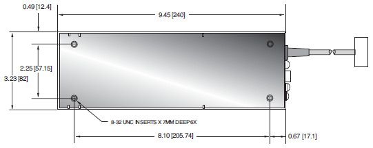
FRONT VIEW