")
SL150kV
- Cable Connected 150kV @ 1200W Power Supply
- Only 8.75"" (5U) Panel Height
- Extensive Analog Interface
- Arc Quench/Count/Trip with Comprehensive Fault Diagnostics
*Note: All specifications are subject to change without notice. Please consult the English PDF version of this datasheet for the most up-to-date revision.


1200W High Voltage Power Supplies
Spellman’s SL150kV rack mount high voltage power supply is designed for scientific and industrial OEM applications requiring 150kV at 1200 watts in a compact cable connected standard sized rack. Models are available in positive, negative or reversible polarity.
The SL150kV rack-mount supply is a cable connected power supply and is fully arc and short circuit protected. Excellent regulation specifications are provided along with outstanding stability performance. The vacuum encapsulated high voltage output section assures reliable corona free operation by eliminating any concerns due to environmental factors.
The typical applications for the SL150kV cable connected, rack-mount power supply are:
- Electrostatics
- HiPot Testing
- Semiconductor Processing
- Capacitor Charging
Specifications
(Ref. 128062-001 REV. M)
Front Panel Controls:
Front Panel Controls Power ON/OFF switch, HV ON
Switch, HV OFF Switch with preset feature, 3.5 digit
backlight digital meters for display of output voltage
and output current,10 turn locking potentiometers with
counting dials for adjustment of both output voltage
and output current.
Front Panel Indicators:
HV ON High Voltage Inhibit
HV OFF Over Current
Voltage Control Mode Over Voltage
Current Control Mode Arc
Interlock Open Regulation Error
Interlock Closed Overtemperature
Input:
220Vac ±10%, 50/60Hz @ 12A
200Vac ±10%, 50/60Hz @ 13.2A
Output Voltage:
0 to 150kV
Output Polarity:
Positive, negative or reversible specify at time of order
Output Current:
8mA
Output Power:
1200W
Voltage Regulation:
Load: 0.01% of rated voltage for a full load change
Line: ±0.01% of rated current over specified input voltage range
Current Regulation:
Load: 0.01% of rated current ±100μA for full voltage change.
Line: ±0.01% of rated current over specified input voltage range
Ripple:
0.1% peak to peak of maximum output
Temperature Coefficient:
100ppm/°C.
Stability:
100ppm/hr after a 2 hour warm up, for both voltage and current regulation
Operating Temperature:
0 to 40°C operating
Storage Temperature:
-40 to +85°C storage
Humidity:
20% to 85%, non-condensing
Input Line Connector:
3 conductor 12 AWG 6 ft (1.83m) cable, permanently attached
Output Connector:
A detachable 10 ft (3.05m) shielded HV cable is provided
Cooling:
Forced Air
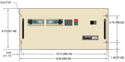
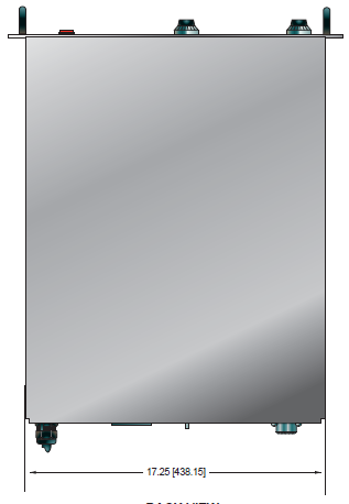
Dimensions:
8.75”H x 19”W x 22”D rack mount. (22.23cm x 48.26cm x 55.88cm)
Weight:
89 pounds (40.4kg)
Regulatory Approvals:
Designed to meet EEC EMC Directive. Designed to meet to EEC Low Voltage Directive. RoHS Compliant.
Options:
200 - 200Vac Input Voltage
AOL - Adjustable Overload Trip
APT - Adjustable Power Trip
AT - Arc Trip
BFP - Blank Front Panel
CPC - Constant Power Control
DPM4 - 4.5 Digit Panel Meters
EFR - External Fault Relay
LL(X) - Non-Standard HV Cable Length (10 standard)
NAD - No Arc Detect
NSS - No Slow Start
RFR - Remote Fault Reset
SS(X) - Non-Standard Slow Start (6 seconds standard)
Electronic Component (Power Source)
SL150KV series is intended for installation as a component of a system. It is designed to meet CE standards, with conditions of acceptance often being: customer provided enclosure mounting, EMC filtering, and appropriate protection, and isolation devices. The SL150KV series is not intended to be operated by end users as a stand-alone device. The SL150KV series power supply can only be fully assessed when installed within a system, and as a component part within that system.
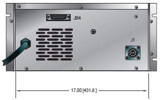
SL150 ANALOG INTERFACE—JB4 25 PIN MALE D CONNECTOR
| Pin | Signal | Parameters |
|---|---|---|
| 1 | Power Supply Common | Signal Ground |
| 2 | External Inhibit | Ground = Inhibit, Open = HV ON |
| 3 | External Interlock | +15Vdc @ open, ≤ 5mA @ closed |
| 4 | External Interlock Return | Connect to pin 3 to enable supply |
| 5 | Current Monitor | 0 to 10Vdc = 0 to 100% rated voltage, Zout =10kΩ |
| 6 | Voltage Monitor | 0 to 10Vdc = 0 to 100% rated voltage, Zout =10kΩ |
| 7 | +10Vdc Reference | +10Vdc @ 1mA, maximum |
| 8 | Remote Current Program Input | 0 to 10Vdc = 0 to 100% rated voltage, Zout =10kΩ |
| 9 | Local Current Program Output | Multi-turn front panel pot for local control capability |
| 10 | Remote Voltage Program Input | 0 to 10Vdc = 0 to 100% rated voltage, Zout =10kΩ |
| 11 | Local Voltage Program Output | Multi-turn front panel pot for local control capability |
| 12 | EFR (Common) | External Fault Relay (Optional) |
| 13 | EFR (Normally Open) | External Fault Relay (Optional) |
| 14 | Local HV OFF OUT | +15Vdc @ open, <25mA @ closed, connect to HV OFF for front panel operation |
| 15 | HV OFF | Connect to HV OFF OUT for front panel operation |
| 16 | Remote HV ON | +15Vdc @ 10mA maximum = HV OFF |
| 17 | Remote HV OFF Indicator | 0 = HV ON, +15Vdc @ 10mA maximum = HV O |
| 18 | Remote HV ON Indicator | 0 = HV OFF, +15Vdc @ 10mA maximum = HV ON |
| 19 | Remote Voltage Mode | Open collector 50Vdc @ 10mA maximum, ON = Active |
| 20 | Remote Current Mode | Open collector 50Vdc @ 10mA maximum, ON = Active |
| 21 | Remote Power Mode | Open collector 50Vdc @ 10mA maximum, ON = Active |
| 22 | Power Supply Fault | Open collector, 50Vdc @ 10mA maximum |
| 23 | +15Vdc Output | +15Vdc @ 100mA, maximum |
| 24 | Power Supply Ground | Signal Ground |
| 25 | Shield Return | Chassis Ground |
Specify “P” for positive polarity or “N” for negative polarity, and PN = reversible as illustrated below.
Sample Model Number: SL150P1200/BFP/LL(20)
Where SL = power supply series, 150 = maximum output voltage in kV,
P = positive output polarity, 1200 = maximum output power (watts), BFP = Blank
Front Panel, LL(20) = 20 foot HV cable.
Tables & Diagrams
DIMENSIONS: in.[mm]
FRONT VIEW
TOP VIEW
BACK VIEW
Frequently Asked Questions
What Is a Safe Level of High Voltage?
What Is an “External Interlock”?
Where Can I Obtain Information on High Voltage Safety Practices?
Can I Operate a High Voltage Power Supply Designed for 220VAC, Single Phase From a 208VAC, Three Phase Electrical Service?
What Kind of High Voltage Connector Do You Use on Your Supplies?
What Do You Mean That the Output Side of the High Voltage Cable on Most Standard Products Is “Unterminated”?
How Should I Ground Your Supply?
Why Is Arcing an Issue for a High Voltage Power Supply?
Application Notes AN-13 – Arc Intervention Circuitry and External Series Limiting Resistors
Application Notes AN-14 – The Limits of Front Panel Digital Meters
Application Notes AN-15 – 3.5 And 4.5 Digit Meter Displays Explained
Application Notes AN-18 – Current Loop/Arc Detection Circuitry
Application Notes AN-19 – High Voltage Cable Lengths Discussed
Application Notes AN-23 – SL HV Off and HV on Circuitry Explained

