")
DGM935
- Multiple Outputs
- Simple Interface Via Three Control Inputs
- Pre set Adjustment of Output Voltages in Four Mode Operation
*Note: All specifications are subject to change without notice. Please consult the English PDF version of this datasheet for the most up-to-date revision.
![]()
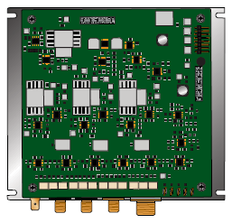
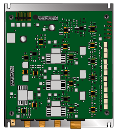
DGM935 Modular High Voltage Supply for Image Intensifiers
Spellman’s new DGM935 high voltage power supply for Image Intensifier applications continues to set the standards for high voltage power conversion technology. The DGM series can be adapted to suit specific requirements with a wide selection of multiple output voltages and power capabilities in a compact package, making it perfect for the OEM user.
Monitoring of all output voltages is possible via local test points. The unit can operate in four modes selectable via three inputs. The output voltages are independently adjustable in each mode by the pre-set potentiometer located on the front of the unit.
Typical applications:
- Radiology
- Cardiology
- Neuroradiology
- Night Surveillance
- Non Destructive X-Ray Inspection
- Image Intensifiers
Specifications
(Ref. 128115-001 REV C)
Input Voltage:
+24Vdc ±1%
Input Current:
500mA maximum
Output Voltages:
Anode:
Output Voltage: 30kV
Output Current: 30µA
Electrode 1:
Output Voltage: 50V to 300V
Output Current: 0 to 1µA
Electrode 2:
Output Voltage: 300V to 2kV
Output Current: 0 to 1µA
Electrode 3:
Output Voltage: 2kV to 18kV
Output Current: 0 to 18µA
Ripple:
<0.3%
Temperature Coefficient:
<200ppmK-1
Stability:
<0.3% over 8 hrs
Temperature:
Operating: +5°C to +55°C
Input:
8 pin header
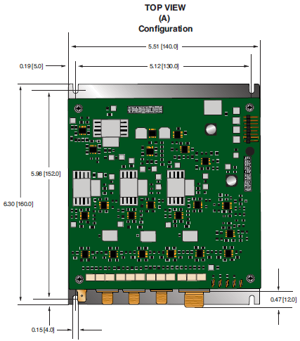
Dimensions:
6.30”H x 5.51”W x 1.93”D (160mm x 140mm x 49mm)
Weight:
2.86 lb. (1.5kg)
Regulatory Approvals:
Compliant to EEC EMC Directive. Compliant to EEC Low Voltage Directive.
INPUT 8 PIN HEADER
| Pin | Signal | Signal Parameters |
|---|---|---|
| 1 | 24V | Power Input |
| 2 | 0V | Power Ground |
| 3 | 0V | Power Ground |
| 4 | 24V | Linked internally to pin1 |
| 5 | M2 | Mode select input 2 |
| 6 | M1 | Mode select input 1 |
| 7 | N/C | N/C |
| 8 | M3 | Mode select input 3 |
Tables & Diagrams
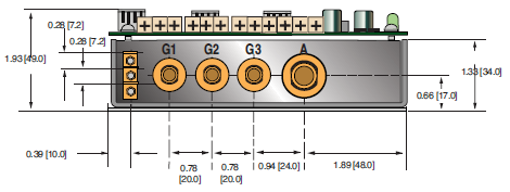
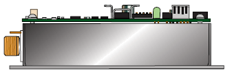
DIMENSIONS: in.[mm]
TOP VIEW
(A)
Configuration
FRONT VIEW
SIDE VIEW
ALTERNATE CONFIGURATIONS AVAILABLE
(Specify at time of order)
(B)
Configuration
(C)
Configuration